Domestic helping omnidirectional mobile robot

An omnidirectional mobile and robotic technology, applied in the field of household support omnidirectional mobile robots, can solve problems such as health hazards and low mobility of wheelchairs, and achieve the effects of reducing space occupation, increasing knee pad structure, and convenient operation

Pending Publication Date: 2018-02-23
HANGZHOU ROBOCT TECH DEV CO LTD
View PDF4 Cites 9 Cited by
  • Summary
  • Abstract
  • Description
  • Claims
  • Application Information

AI Technical Summary

Problems solved by technology

[0003] In order to solve the problems of low mobility of conventional wheelchairs and great harm to health caused by si...

Method used


Image

  • Domestic helping omnidirectional mobile robot
  • Domestic helping omnidirectional mobile robot
  • Domestic helping omnidirectional mobile robot

Examples


specific Embodiment approach 1

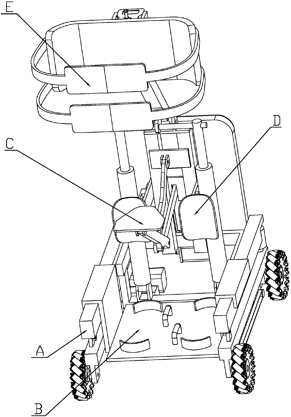
[0027] Specific implementation mode one: combine Figure 1 to Figure 12 To illustrate the present embodiment, the present embodiment includes chassis A, foot support plate B, seat telescopic mechanism C, knee support mechanism D and chest support mechanism E,

[0028] Two mecanum wheels 2 are respectively arranged on the front and rear sides of the chassis A, and each mecanum wheel 2 is driven by a motor reducer I3,

[0029] The foot support plate B is arranged on the chassis A,

[0030] Seat retractable mechanism C comprises seat 15, long connecting rod 16, bent connecting rod 17, short connecting rod 18 and column 19, and one end of long connecting rod 16 is affixed together with the bottom of seat 15, and column 19 front and rear sides Respectively be provided with hinged plate, short connecting rod 18 two ends are respectively hinged with the hinged plate on one side of column 19 and the other end of long connecting rod 16, and the two ends of curved connecting rod 17 are...

specific Embodiment approach 2

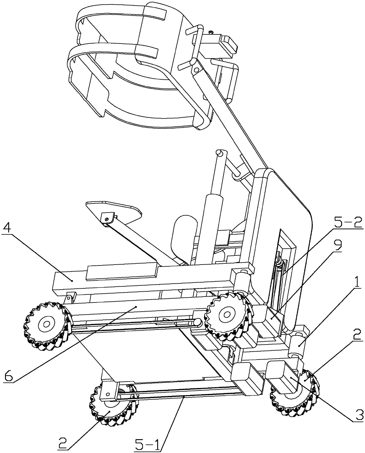
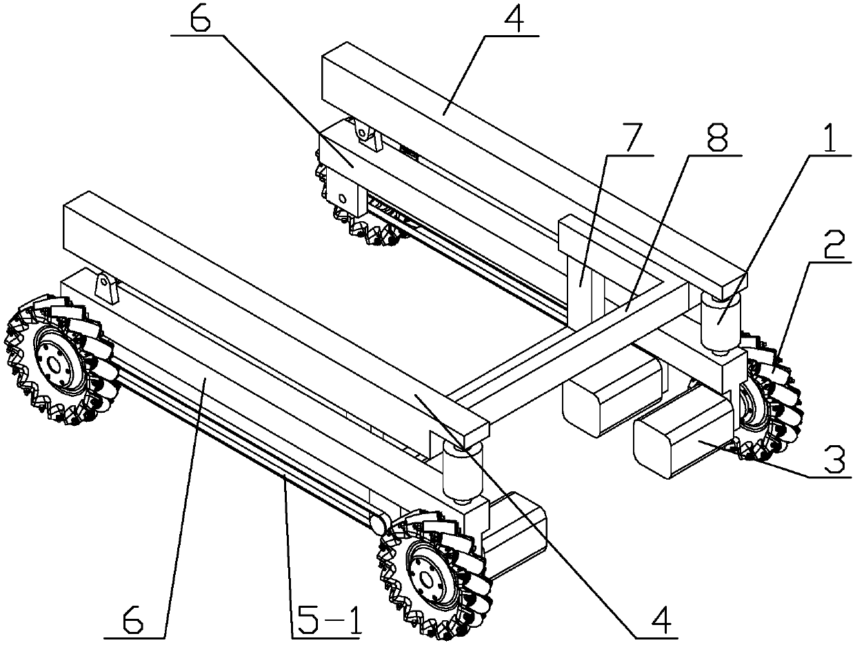
[0033] Specific implementation mode two: combination image 3 To illustrate this embodiment, the chassis A of this embodiment includes an upper beam 8, a lower beam 7, two lower rods 6 and two upper rods 4,

[0034] The upper beam 8 and the lower beam 7 are fixed together, the upper beam 8 is provided with a control box 24, two upper long rods 4 and two lower long rods 6 are symmetrically arranged on both sides of the upper beam 8, and the two upper long rods 4 Respectively fixed together with the upper beam 8, one end of each lower long bar 6 is hinged with one end of each upper long bar 4 respectively, the other end of each lower long bar 6 and the other end of each upper long bar 4 A damping spring 1 is arranged between them, and a mecanum wheel 2 is respectively arranged at both ends of each lower long rod 6,

[0035] The Mecanum wheel 2 arranged adjacent to the shock absorbing spring 1 is directly connected to the motor reducer I3, and the Mecanum wheel 2 arranged adjace...

specific Embodiment approach 3

[0036] Specific implementation mode three: combination Figure 4 To illustrate this embodiment, the sole support plate B of this embodiment includes a load-bearing plate 14, a U-shaped handle I13 and two pairs of foot fixing brackets 12, the load-bearing plate 14 is a square, and the two pairs of foot fixing brackets 12 are arranged side by side on the load-bearing plate 14 Two U-shaped handles I13 are provided on the upper surface of the load-bearing plate 14, and two symmetrical hook-shaped hanging plates 11 are affixed to both sides of the load-bearing plate 14, and the hanging plates 11 on both sides of the load-bearing plate 14 are respectively connected to the two 4 fastenings on the upper pole.

[0037] Preferably, the foot fixing brackets 12 are arc-shaped plates, and the concave surfaces of each pair of the foot fixing brackets 12 are arranged opposite to the concave surfaces.

[0038] In this embodiment, the foot support B is removed to switch to the training mode, ...


PUM


Abstract

The invention provides a domestic helping omnidirectional mobile robot, which relates to a robot and solves the problems that the movability of a conventional wheelchair is low, and great harm is caused on the health after people sit the wheelchair for a long period. The front side and the back side of a base plate of the mobile robot are provided with two Mecanum wheels; each Mecanum wheel is singly driven by a motor speed reducer I; a foot sole carrying plate is arranged on the base plate; one end of a long connecting rod is fixedly connected with the bottom of a seat; a hinging plate is arranged at each of the front side and the back side of an upright post; the two ends of a short connecting rod are respectively hinged to the hinging plate arranged at one side of the upright post and the other end of the long connecting rod; the two ends of a bent connecting rod are respectively hinged to the hinging plate arranged at the other side of the upright post and the long connecting rod;the upright post is fixedly connected onto the base plate; an execution mechanism I drives the short connecting rod, so that the seat can swing, and extend and retract backwards and backwards; a kneesupporting protection plate is provided with a regulating rod; a knee supporting lengthening device is fixed on the upright post, so that a regulating rod of the knee supporting protection plate is buckled on the upright post in a sleeving way. The domestic help omnidirectional mobile robot is applicable to old people, disabled people and paralyzed people inconvenient to move.

Description

technical field [0001] The invention relates to a robot, in particular to an omnidirectional mobile robot for household assistance. Background technique [0002] At present, most of the elderly, disabled, and paralyzed patients with limited mobility generally need specialized personnel to take care of them in their daily lives, and cannot take care of their normal daily life. Common mobility aids on the market generally include wheelchairs and electric wheelchairs, although to a large extent It helps travel, but sitting in a wheelchair for a long time will lead to blood blockage, pressure sores, osteoporosis and other complications, which will have a great impact on health. inconvenience. Contents of the invention [0003] In order to solve the problems of low mobility of conventional wheelchairs and great harm to health caused by sitting in wheelchairs for a long time, the present invention provides an omnidirectional mobile robot for household assistance. [0004] The ...

Claims


Application Information

Patent Timeline
IPC IPC(8): A61H3/04
CPCA61H3/04A61H2201/1207
Inventor 王天王晓奇孙相宇
Owner HANGZHOU ROBOCT TECH DEV CO LTD
Why Eureka
Try Eureka