
Gas-liquid separation device used for chemical industry

A technology of gas-liquid separation device and exhaust device, applied in separation methods, liquid degassing, chemical instruments and methods, etc., can solve the problems of expanding the fluctuation of fluid flow, reducing the quality of chemical products, affecting the economic benefits of enterprises, etc. Improves stability, eliminates poor fluid transport, and facilitates job guidance

Inactive Publication Date: 2018-02-23
新昌县中申制冷配件厂
View PDF0 Cites 0 Cited by
  • Summary
  • Abstract
  • Description
  • Claims
  • Application Information

AI Technical Summary

Problems solved by technology

[0002] The fluid at the input end of the pipeline transportation is affected by the pressure and dissolves more gas than under normal pressure, while the pressure on the fluid in the pipeline gradually decreases, releasing excess gas that cannot be dissolved. The effect of gas on fluid transportation in large-diameter pipelines The impact is small, and the gas in the large-diameter pipeline is generated quickly, which is easy to handle, while the gas in the small-diameter pipeline will often block the pipeline, affect the transportation of the fluid, expand the fluctuation of the fluid flow rate, increase the wear rate of the pipeline, and reduce the chemical products. The quality of the enterprise affects the economic benefits of the enterprise

Method used


Image

  • Gas-liquid separation device used for chemical industry
  • Gas-liquid separation device used for chemical industry

Examples


Embodiment Construction

[0015] The following will clearly and completely describe the technical solutions in the embodiments of the present invention with reference to the accompanying drawings in the embodiments of the present invention. Obviously, the described embodiments are only some, not all, embodiments of the present invention.

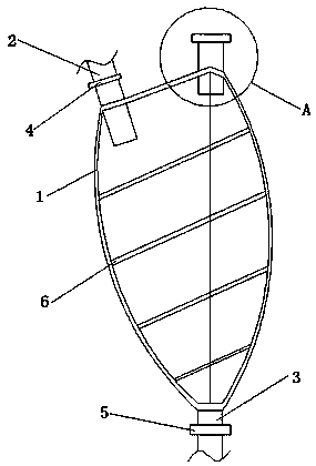
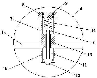
[0016] refer to Figure 1-2 , a gas-liquid separation device for chemical industry, including a bag body 1 and an exhaust device 7, a through hole is opened on one side of the bag body 1 and a feed pipe 2 is inserted in the through hole, and the feed pipe 2 is in the bag One end outside the body 1 is provided with a first cut-off valve 4, the bottom end of the bag body 1 has a through hole and a discharge pipe 3 is inserted in the through hole, and the discharge pipe 3 is provided with a valve at one end outside the bag body 1. The second stop valve 5, the top of the bag body 1 has a through hole and an exhaust device 7 is inserted in the through hole, and the inside...


PUM


Abstract

The invention discloses a gas-liquid separation device used for chemical industry. The gas-liquid separation device comprises a bag body and an exhaust unit, wherein a feeding pipe is inserted at oneside of the bag body; meanwhile, one end of the feeding pipe located outside of the bag bog is provided with a first stop valve; a discharging pipe is inserted at the bottom end of the bag body; meanwhile, one end of the discharging pipe located outside of the bag body is provided with a second stop valve; the exhaust unit is inserted at the top part of the bag body; meanwhile, the interior of thebag body along the width direction is provided with annular elastic supports; the exhaust unit comprises a dustproof cover plate, dustproof nets, a card slot, a support rod, a card block, a limit block, a spring and a shell; the top end of the shell is fixedly provided with the dustproof cover plate; the interior of the dustproof cover plate is provided with the dustproof nets; the bottom end ofthe dustproof cover plate is provided with the spring; one end of the spring is connected with the support rod; the bottom end of the support rod is fixedly provided with the card block through a screw; and the central part of the shell is provided with the limit block. The gas-liquid separation device provided by the invention is simple and convenient to operate, and can guarantee a stable flow rate of a raw material during gas-liquid separation.

Description

technical field [0001] The invention relates to the technical field of gas-liquid separation, in particular to a gas-liquid separation device for chemical industry. Background technique [0002] The fluid at the input end of the pipeline transportation is affected by the pressure and dissolves more gas than under normal pressure, while the pressure on the fluid in the pipeline gradually decreases, releasing excess gas that cannot be dissolved. The effect of gas on fluid transportation in large-diameter pipelines The impact is small, and the gas in the large-diameter pipeline is generated quickly, which is easy to handle, while the gas in the small-diameter pipeline will often block the pipeline, affect the transportation of the fluid, expand the fluctuation of the fluid flow rate, increase the wear rate of the pipeline, and reduce the chemical products. The quality of the product affects the economic benefits of the enterprise. Contents of the invention [0003] The purpo...

Claims


Application Information

Patent Timeline
Patent Type & Authority Applications(China)
IPC IPC(8): B01D19/00
CPCB01D19/00
Inventor 张海东
Owner 新昌县中申制冷配件厂
Learn More