Eddy current air inflow type nozzle for spraying release agent

A type of release agent and air-intake technology, which is applied in the direction of injection devices and liquid injection devices, can solve the problems of long response time of nozzle opening and closing, excessive disturbance of release agent liquid, etc., achieve good response time, reduce pollution, and save energy. The effect of dosage

Pending Publication Date: 2018-02-23
YUTAKA ELECTRONICS SH
6 Cites 0 Cited by

AI-Extracted Technical Summary

Problems solved by technology

[0004] The technical problem to be solved by the present invention is to provide a vortex air-intake type release agent spraying nozzle with good response time, improved economic benefit, and reduced environmental pollution, which solves the current problem of using solenoid valves to indirectly control ...

Method used

[0036] When the electromagnetic nozzle was in a de-energized state, the moving iron core 14 was in contact with the boss 25, which could more reliably close the release agent passage (ie the aperture 20 at the front end of the atomizing head 2). The atomizing gas channels of the atomizing head 2 are designe...

Abstract

The invention discloses an eddy current air inflow type nozzle for spraying a release agent. The eddy current air inflow type nozzle is characterized in that the eddy current air inflow type nozzle comprises an atomization head and a movable iron core. The atomization head is arranged in a nozzle cap, the nozzle cap is connected with a front valve body through a thread, the atomization head is clamped between the nozzle cap and the front valve body, and the front section of the movable iron core is arranged in the atomization head; the middle section of the movable iron core penetrates throughthe front valve body, the rear section of the movable iron core is arranged in a guide sleeve, and a coil framework is arranged on the rear face of the guide sleeve; the coil framework is wound witha coil, the coil framework is arranged in a rear shell, and a static iron core is arranged in the coil framework; and the rear end of the static iron core is clamped between the coil framework and therear shell through a shaft shoulder, the rear section of the guide sleeve is further arranged in the coil framework, and an electromagnetic coil wiring outlet is formed in the bottom face of the rearshell. According to the eddy current air inflow type nozzle for spraying the release agent, the nozzle has good response time, the actual requirements can be met, the using amount of the release agent can be reduced, the economic benefits of enterprises are improved, and the pollution to the environment is greatly relieved.

Application Domain

Liquid spraying apparatus

Technology Topic

PhysicsMagnet coil +5

Image

  • Eddy current air inflow type nozzle for spraying release agent
  • Eddy current air inflow type nozzle for spraying release agent
  • Eddy current air inflow type nozzle for spraying release agent

Examples

  • Experimental program(3)

Example Embodiment

[0031] Example 1
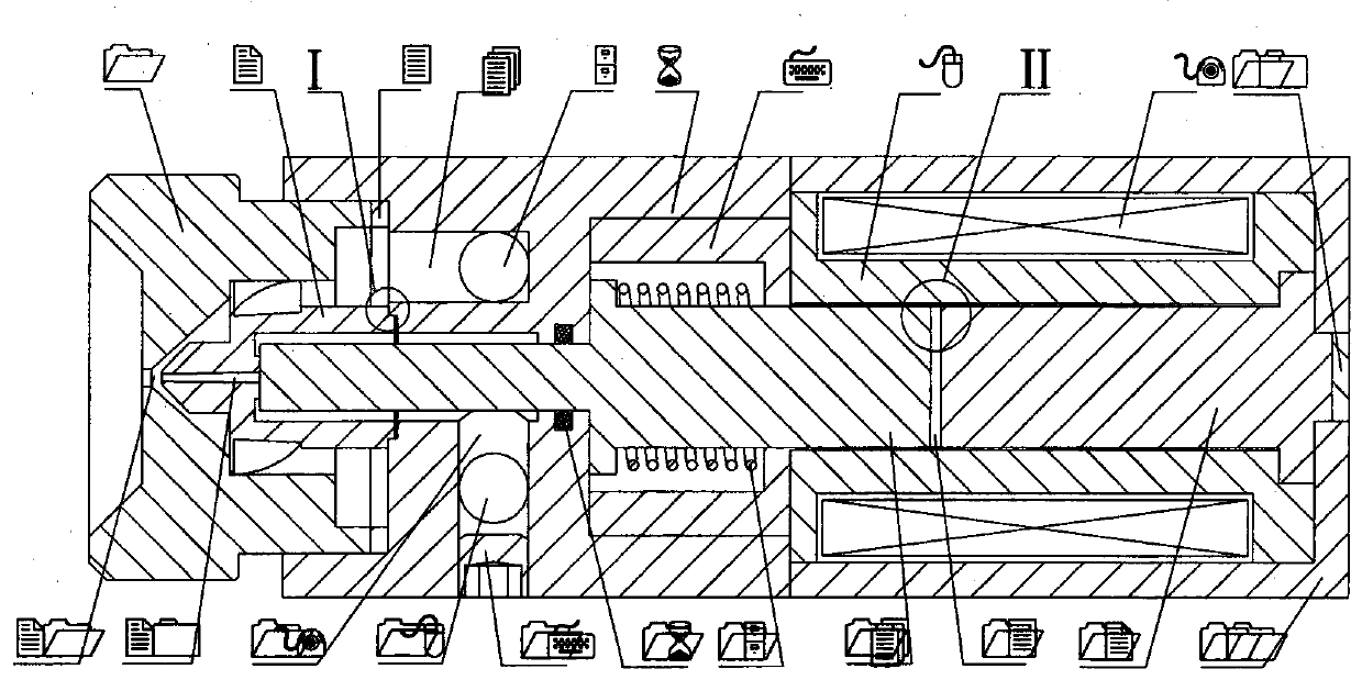
[0032] The present invention is a nozzle for spraying vortex air intake type release agent, such as figure 1 As shown, it consists of nozzle cover 1, atomization head 2, gasket 3, front valve body 6, guide sleeve 7, coil frame 8, coil 9, sealing cover 10, rear housing 11, static iron core 12, moving iron core 14. Spring 15, sealing ring 16, set screw 17, etc. The atomization head 2 is arranged inside the nozzle cover 1. The nozzle cover 1 and the front valve body 6 are connected by threads, and the atomization head 2 is clamped between the nozzle cover 1 and the front valve body 6, as figure 2 Shown. The valve core of the nozzle part and the armature of the electromagnetic control part are made as a whole, namely the movable iron core 14. The front section of the moving iron core 14 is arranged inside the atomizing head 2, the middle section of the moving iron core 14 passes through the front valve body 6, and the rear section of the moving iron core 14 is arranged inside the guide sleeve 7. Such as image 3 As shown, the thickness of the thin wall of the guide sleeve 7 is 0.15 mm. The guide sleeve 7 and the front valve body 6 are connected by interference fit. A coil bobbin 8 is provided, and the coil 9 is wound on the coil bobbin 8, such as Figure 4a , Figure 4b Shown. The bobbin 8 is provided inside the rear housing 11. The static iron core 12 is arranged inside the coil bobbin 8, and the rear end of the static iron core 12 is clamped between the coil bobbin 8 and the rear housing 11 through a shaft shoulder. The rear section of the guide sleeve 7 is also arranged inside the coil bobbin 8, such as Figure 5 Shown. The movable iron core 14 is always located in the guide sleeve 7, the thin wall of the guide sleeve 7 is in contact with the coil frame 8, and the movable iron core 14 does not contact the coil frame 8. The bottom surface of the rear housing 11 is provided with an electromagnetic coil wiring outlet 23, and the rear end of the rear housing 11 has two through holes 24, such as Image 6 As shown, the front valve body 6 has two first threaded holes at the corresponding connection positions, the front valve body 6 and the rear housing 11 are connected by a stud, and the stud passes through the through hole 24 to connect with the first threaded hole.
[0033] There is a gap between the moving iron core 14 and the static iron core 12, which is the air gap 13; when the nozzle is closed, such as figure 1 As shown, if energized, the moving iron core 14 will move backward and move within the range of the air gap 13.
[0034] A spring 15 is sleeved on the rear section of the movable iron core 14 inside the guide sleeve 7, a gasket 3 is provided between the end of the nozzle cover 1 and the front valve body 6, and the end of the rear housing 11 is provided with a sealing cover 10, and the movable iron A sealing ring 16 is provided between the middle section of the core 14 and the front valve body 6, and an atomization outlet 21 is provided at the front of the nozzle cover 1.
[0035] Such as Figure 7a-Figure 7d As shown, the front end of the atomization head 2 is provided with a small hole 20, the inside of the atomization head 2 is provided with a boss 25, the small hole 20 is provided in the middle of the boss 25, and the outside of the atomization head 2 is provided with 3-6 A uniformly distributed spiral channel 28. In this embodiment, the outer side of the atomization head 2 is provided with 4 evenly distributed spiral channels 28.
[0036] When the electromagnetic nozzle is in a power-off state, the movable iron core 14 is in contact with the boss 25, which can more reliably close the release agent channel (that is, the small hole 20 at the front end of the atomizing head 2). The atomizing gas channel of the atomizing head 2 is designed as four spiral channels 28 distributed symmetrically. The spiral channel 28 can guide the originally linearly moving atomizing gas into a rapidly rotating and turbulent airflow, which can produce a better atomization effect after being mixed with the release agent.
[0037] Such as Figure 8a-Figure 8c As shown, the front end surface of the front valve body 6 is provided with four second threaded holes 22 for positioning and installing the electromagnetic nozzle. A release agent channel 19 is opened on the side of the front valve body 6. Due to the needs of parts processing, the release agent channel 19 is designed as a through hole, and a set screw 17 is installed in the release agent channel 19. The bottom surface of the front valve body 6 is provided with a release agent radial channel 18 and an atomizing gas radial channel 5. The front valve body 6 is provided with a release agent axial channel 26 in the middle. The release agent axial channel 26 communicates with the release agent radial channel 18. The front valve body 6 has grooves at the front and back ends. 6 An atomizing gas axial channel 4 is provided in the slot at the front end of the slot, and the atomizing gas axial channel 4 and the atomizing gas radial channel 5 are connected. The middle of the front valve body 6 is provided with a groove 27 into which the sealing ring 16 can prevent the release agent liquid from entering the rear section of the electromagnetic nozzle. The groove 27 is provided in the passage between the groove at the rear end of the front valve body 6 and the release agent axial passage 26.
[0038] The invention can increase the mixing space at the atomization outlet 21, so that the atomization gas and the release agent solution are more fully mixed before spraying, so as to achieve the effect of preliminary atomization. The electromagnetic force can be increased, and the winding shape of the coil bobbin 8 can be changed from rectangular to circular.

Example Embodiment

[0039] Example 2
[0040] In this embodiment, three evenly distributed spiral channels 28 are provided on the outside of the atomization head 2. Others are the same as the embodiment.

Example Embodiment

[0041] Example 3
[0042] In this embodiment, six evenly distributed spiral channels 28 are provided on the outside of the atomization head 2. Others are the same as the embodiment.

PUM

PropertyMeasurementUnit
Thickness0.15mm

Description & Claims & Application Information

We can also present the details of the Description, Claims and Application information to help users get a comprehensive understanding of the technical details of the patent, such as background art, summary of invention, brief description of drawings, description of embodiments, and other original content. On the other hand, users can also determine the specific scope of protection of the technology through the list of claims; as well as understand the changes in the life cycle of the technology with the presentation of the patent timeline. Login to view more.

Similar technology patents

Hybrid direct-current circuit breaker

ActiveUS20160105018A1reduce footprintgood response time
Owner:GENERAL ELECTRIC CO

Enterprise operational indicator target quantity determining method and device

InactiveCN106651148Agood response timeImprove work efficiency
Owner:STATE GRID ENERGY RES INST

Preparation method of ultrahigh molecular weight polyethylene fiber

ActiveCN101768786AReduced breaking strengthreduce dosage
Owner:CHANGSHU SUPERFIBER

Method and system for manipulating labelled data for data entry in management applications

InactiveUS20050010862A1not jeopardize response timegood response time
Owner:KYNDRYL INC

Classification and recommendation of technical efficacy words

  • good response time
  • reduce dosage

Method and system for manipulating labelled data for data entry in management applications

InactiveUS20050010862A1not jeopardize response timegood response time
Owner:KYNDRYL INC

Hybrid direct-current circuit breaker

ActiveUS20160105018A1reduce footprintgood response time
Owner:GENERAL ELECTRIC CO

Enterprise operational indicator target quantity determining method and device

InactiveCN106651148Agood response timeImprove work efficiency
Owner:STATE GRID ENERGY RES INST

High-performance recovered PET/ABS alloy

Owner:SOUTH CHINA NORMAL UNIVERSITY

Reverse osmosis membrane scale inhibitor and preparation and use method thereof

ActiveCN101423299AGood anti-scaling effectReduce dosage
Owner:CHINA PETROLEUM & CHEM CORP +1

Selective hydrogenation catalyst of alkine and diolefin, preparation method and application

ActiveCN1958155AImprove hydrogenation efficiencyreduce dosage
Owner:CHINA PETROLEUM & CHEM CORP +1
Why Eureka
Try Eureka