Cutting device of iron wire feather duster handle

A cutting device and a technology for a hair duster, which are applied to the field of cutting devices for a wire brush handle, can solve the problems of time-consuming and labor-intensive, low production efficiency, insufficient automation, etc. The effect of production efficiency

Pending Publication Date: 2018-02-23
CHANGSHAN XINHUI CLEANING SUPPLIES
View PDF2 Cites 2 Cited by
  • Summary
  • Abstract
  • Description
  • Claims
  • Application Information

AI Technical Summary

Problems solved by technology

[0003] The Chinese patent CN205799654U is published, including a bracket and a cutting platform. One side of the cutting platform is provided with a cutting knife, and the other side of the cutting platform is provided with a contact sensor. The cutting knife is connected with the driving gear, and the driving gear drives the cutting knife to rotate. A drive motor is provided below, and the drive motor is connected to the drive gear through a reduction mechanism. The contact sensor includes a rotating rod that is movably connected to the cutting platform, and a fixed baffle is fixed on the rotating rod. One side of the cutting platform is equipped with an electronic infrared sensor. Inductive switch, when the end of the plastic tube touches the contact sensor, first the end of the plastic tube contacts the fixed baffle, the fixed baffle starts to rotate and sweeps the infrared rays of the electronic infrared sensor switch, at this time, the controller receives The signal to the electronic infrared senso

Method used


Image

  • Cutting device of iron wire feather duster handle

Examples


Embodiment 1

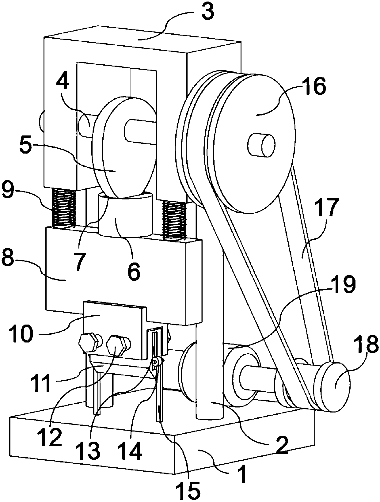
[0021] like figure 1 As shown in the three-dimensional structure diagram of the wire wool duster handle cutting device, a wire wool duster handle cutting device includes a base 1, a support rod 2 is arranged on the base 1, and a support frame 3 is fixed on the upper end of the support rod 2. The support frame 3 is equipped with a rotating shaft 4, the rotating shaft 4 is provided with a cam 5, and the cam 5 can rotate in the cam track 7 of the cam support shaft 6, and the cam support shaft 6 is fixed on the support plate 8, so A strong spring 9 is installed between the support plate 8 and the support frame 3, a cutter holder 10 is installed below the support plate 8, a cutter 11 is housed on the cutter holder 10, and the cutter 11 is fixed by Screw 12 is fixed, and described cutter 11 two sides are provided with cutter moving groove 13, and described cutter moving groove 13 links to each other with roller 14, and described roller 14 is installed on the roller support bar 15, a...


PUM


Abstract

The invention relates to a cutting device of an iron wire feather duster handle. The cutting device comprises a base. The base is provided with a supporting rod. The upper end of the supporting rod isfixedly provided with a supporting frame. The supporting frame is provided with a rotating shaft. A cam is arranged on the rotating shaft. The cam can rotate in a cam track of a cam supporting shaft.The cam supporting shaft is fixed on a supporting plate. A high-strength spring is arranged between the supporting plate and the supporting frame. A cutter fixing frame is arranged below the supporting plate. The cutter fixing frame is provided with a cutter. The cutter is fixed through fixing screws. Cutter moving grooves are formed in the two side surfaces of the cutter and connected with a roller. The roller is mounted on a roller supporting rod. The roller supporting rod is fixed on the base. One end of the rotating shaft is provided with a power rotating wheel. The power rotating wheel is provided with a belt. The other end of the belt is mounted on a transmission wheel. The transmission wheel is mounted on a motor. The cutting device is simple in structural design, problems such asuneven cutting force can be avoided, the production efficiency is improved, and the practicability is high.

Description

technical field [0001] The invention belongs to the field of wire cutting equipment, and mainly relates to a wire brush handle cutting device. technical background [0002] Feather duster, as the name suggests, is a duster made of chicken feathers, with a stick as the main body, and a lot of chicken feathers plugged in around it. It can be used to clean all kinds of furniture, electrical appliances, etc., and the chicken feathers are colorful, which is more beautiful because the chicken feathers are not Dust, electrostatic effect, the feather duster generates static electricity to absorb dust through friction, it can brush the dust on the surface of the object, no need to wipe it with a damp cloth, just hit it a few times, and the brush will be clean, very convenient. In practical applications, due to the wider sources of man-made materials such as fibers and wool, the materials used to make wool dusters are not limited to chicken feathers, and the sticks used to fix chicken...

Claims


Application Information

Patent Timeline
IPC IPC(8): B21F11/00
CPCB21F11/00
Inventor 金允明
Owner CHANGSHAN XINHUI CLEANING SUPPLIES
Why Eureka
Try Eureka