Measurement device and method used for screen printing machine and stencil printing machine

A technology of stencil printing machine and screen printing machine, which is applied to the general parts of printing machinery, printing machines, printing, etc., and can solve the problems of unusable

Active Publication Date: 2018-02-23
CETAQ GMBH
View PDF5 Cites 0 Cited by
  • Summary
  • Abstract
  • Description
  • Claims
  • Application Information

AI Technical Summary

Problems solved by technology

Errors in printing lead to consequences and unusable wiring supports or products

Method used


Image

  • Measurement device and method used for screen printing machine and stencil printing machine
  • Measurement device and method used for screen printing machine and stencil printing machine
  • Measurement device and method used for screen printing machine and stencil printing machine

Examples


Embodiment Construction

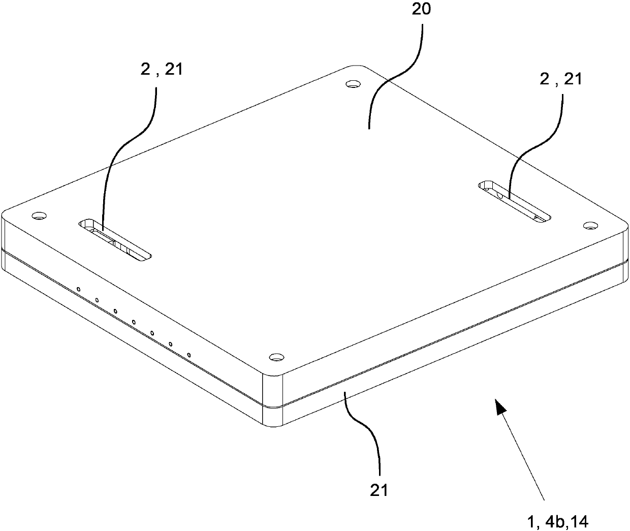
[0039] figure 1 A light transmission is shown of a measuring device 1 integrated in a force measuring plate 14 comprising two camera units 2 for use in a screen printing machine or a stencil printing machine (not shown).

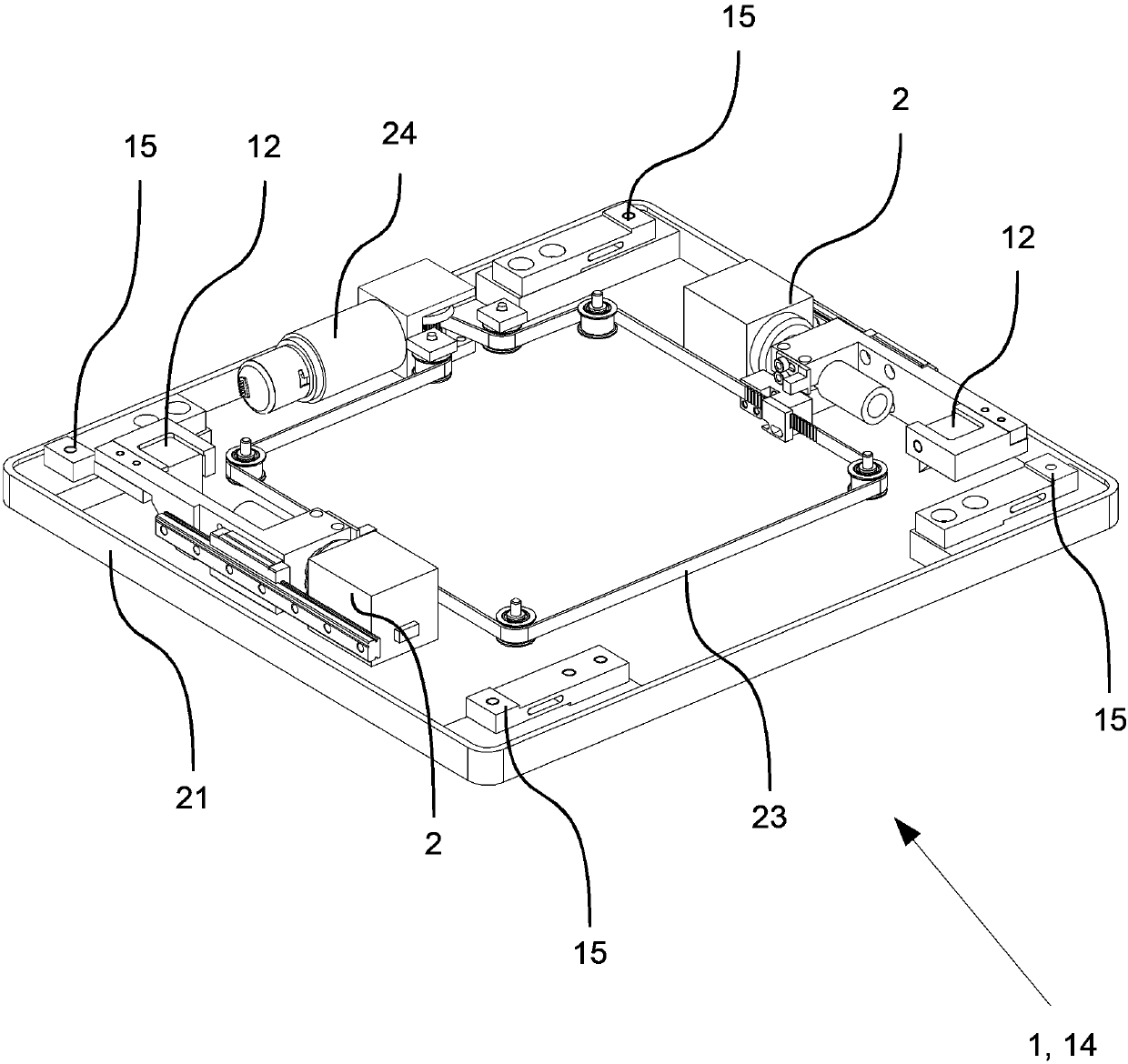
[0040] In principle, it is advantageous that the measuring device 1 can be integrated in the plate-shaped wiring carrier receptacle 4b. In order to be able to use the assembly and at the same time also determine the scraper pressure, the optical measuring device 2 is integrated in the force-measuring plate 14 serving as the wiring carrier support 4 b.

[0041] In the force measuring plate 14, between the cover plate 20 and the base plate 21, the force sensor 15 (in the figure 1 not shown). Optical measuring device 2 includes two camera units 2 arranged in measuring device 1 . For this purpose, corresponding openings 22 are provided in the cover plate 20 of the measuring device 1, said openings enabling the optical detection of the glass measuring plate ly...


PUM


Abstract

The invention relates to a measurement device and method used for a screen printing machine and a stencil printing machine. The deviation and the machine performance values of a final printer are measured rapidly, simply and reliably and used for accurately orienteering a wiring bearing relative to a printing die. At the same time, detection of a force-time-change curve on the printed face and selectively common analysis treatment can be achieved. The measurement method for the screen printing machine and the stencil printing machine by aid of the measurement device arranged below the printedplane comprises the step that the measurement device detects at least two marks on a measurement board in a printed object in relevant with corresponding reference marks of the printing die attachingto the measurement board by aid of camera units in the printing period and / or when the printing period is over, and measures the deviations in the X direction and the Y direction between the marks andthe corresponding reference marks.

Description

technical field [0001] The invention relates to a measuring method and an associated measuring device for screen printing machines and stencil printing machines. The invention is especially intended for use in screen printing machines and stencil printing machines for quality assurance. [0002] For automated manufacture of wired standoffs It is important to print wiring supports, such as printed circuit boards, with a printing medium, such as solder paste. It is important here that the printing medium is applied precisely at the correct point on the wiring carrier. Printing takes place by means of a die, such as a printing screen or a printing template, and a squeegee moving over it, which presses the printing medium through openings provided in the die and thus applies it to the wiring carrier. [0003] The invention stipulates that the measuring device arranged between the stamp and the machine table is provided with at least one camera unit for detecting the position o...

Claims


Application Information

Patent Timeline
IPC IPC(8): B41F33/00
CPCB41F33/0036
Inventor H·豪普特M·凯尔
Owner CETAQ GMBH
Why Eureka
Try Eureka