Split main speed reducer

A main reducer, split technology, applied in the direction of electric power device, control device, power device, etc., can solve the problems of large space occupation, affecting the use of vehicle space, etc., to avoid space occupation, improve the actual load rate, and ensure the transmission efficiency effect

Pending Publication Date: 2018-02-23
FUJIAN WANRUN NEW ENERGY TECH
View PDF5 Cites 0 Cited by
  • Summary
  • Abstract
  • Description
  • Claims
  • Application Information

AI Technical Summary

Problems solved by technology

[0004] For this reason, it is necessary to provide a split final reducer to solve the problem that the power input shaft and the output shaft are vertically arranged in the prior art, which causes a large space occupation and affects the use of vehicle space.

Method used


Image

  • Split main speed reducer

Examples


Embodiment Construction

[0024] In order to explain in detail the technical content, structural features, achieved goals and effects of the technical solution, the following will be described in detail in conjunction with specific embodiments and accompanying drawings.

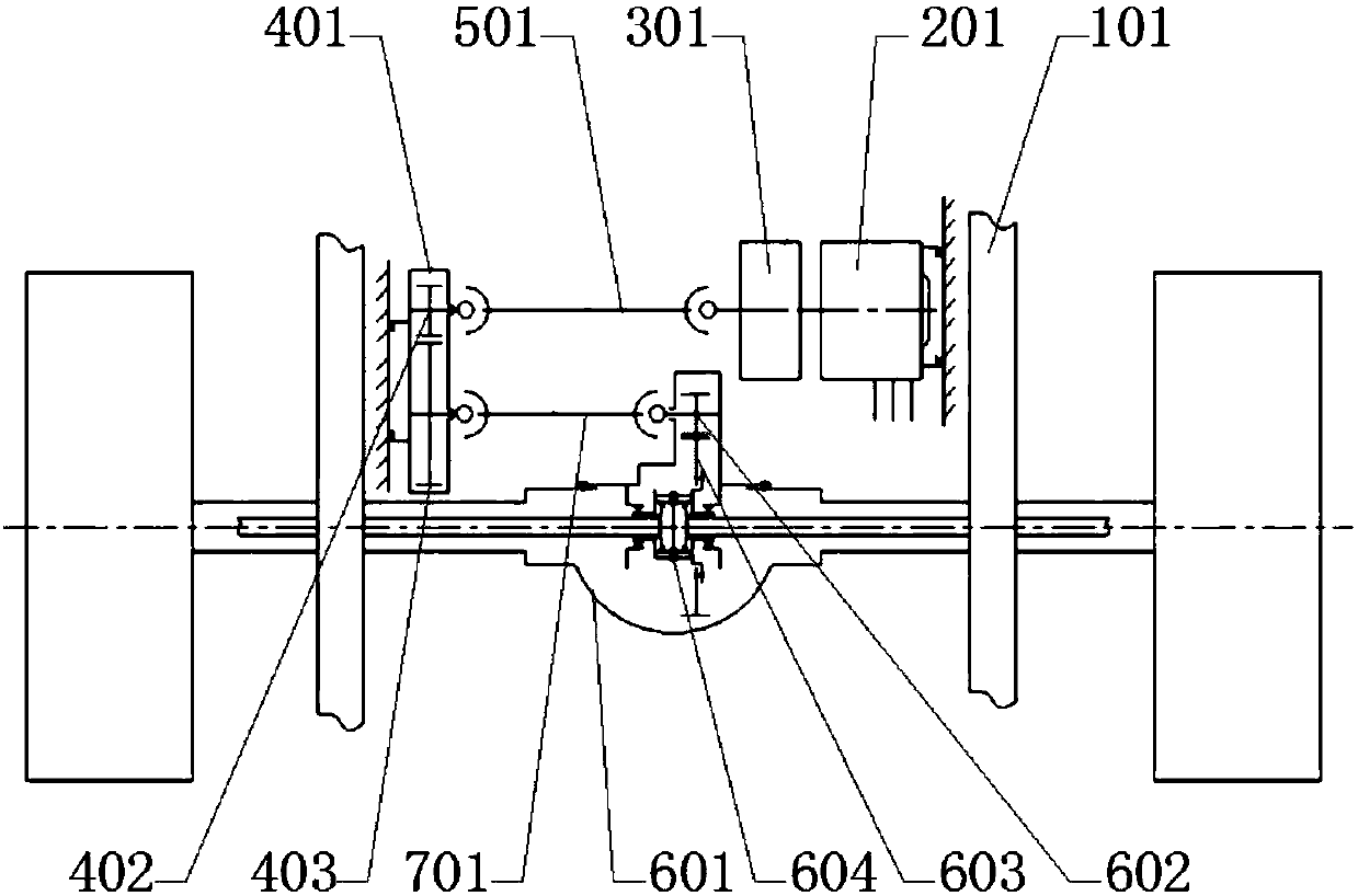
[0025] see figure 1 , this embodiment discloses a split-type main reducer, the power unit 201 and the transmission 301 are connected to one side of the vehicle body 101 (in this embodiment, the power unit transmits power to the first transmission shaft after being shifted by the transmission) . The power unit 201 is in transmission connection with the power input end of the transmission 301 , and the first speed reducer 401 is connected to the other side of the vehicle body 101 and includes a first transmission gear 402 and a second transmission gear 403 . The first transmission gear 402 is in transmission connection with the power output shaft of the transmission 301 through the first transmission shaft 501 , and the second transmis...


PUM


Abstract

The invention discloses a split main speed reducer, which comprises a first speed reducer, a first transmission shaft, a second speed reducer and a second transmission shaft, wherein the first speed reducer is connected onto one side of a vehicle body or an axle, and comprises a first transmission gear and a second transmission gear; the first transmission gear is in transmission connection with apower device through the first transmission shaft; the second speed reducer comprises a third transmission gear, a fourth transmission gear and a differential mechanism; the first transmission shaftand the second transmission shaft are all in transverse arrangement. The main speed reducer is divided into two parts including the first speed reducer and the second speed reducer, so that a power input shaft and a power output shaft are parallel; the occupation of a great space due to the use of mutually vertical power input shaft and power output shaft can be avoided; the space arrangement in the vehicle is convenient, so that the minimum length of the first transmission shaft and the second transmission shaft can be ensured; the problems that when the power device is transversely arranged,the width occupation of the vehicle body is great, and too great transmission shaft setting angle or too short length can occur during direct connection with the differential mechanism can be solved.

Description

technical field [0001] The invention relates to the technical field of vehicle structures, in particular to a split final reducer. Background technique [0002] In existing vehicles, passenger cars, especially large passenger cars, the final reducer usually consists of a pair of bevel gears whose input and output axes are vertically arranged. This type of arrangement requires that the rotating shaft of the power device (engine, or motor) be arranged vertically, that is, arranged parallel to the driving direction of the vehicle. Because the engine of a passenger car is generally arranged at the position of the rear axle, the vertical arrangement of the power unit results in a long rear overhang of the vehicle, which is not conducive to improving the actual load rate of the vehicle. In the field of new energy vehicles, due to the existence of the vertical transmission shaft, the battery needs to make way for the transmission shaft, which is not conducive to the layout of the ...

Claims


Application Information

Patent Timeline
Patent Type & Authority Applications(China)
IPC IPC(8): B60K17/08B60K1/00
CPCB60K1/00B60K17/08
Inventor 黄键吴勇徐世跃
Owner FUJIAN WANRUN NEW ENERGY TECH
Why Eureka
Try Eureka