Method for adjusting rigidity of axle box positioning node with sectioning jackets and axle box positioning node

A technology of positioning nodes and adjustment methods, which is applied in the directions of axle box installation, railway car body parts, bogies, etc., can solve the problem of the large range of rigidity requirements of axle box positioning nodes in all directions, and achieves expansion of the scope of use and adjustable range. Effect

Pending Publication Date: 2018-02-23
ZHUZHOU TIMES RUIWEI ANTI VIBERATION EQUIP LTD
View PDF8 Cites 5 Cited by
  • Summary
  • Abstract
  • Description
  • Claims
  • Application Information

AI Technical Summary

Problems solved by technology

[0010] Aiming at the problem that the current technology cannot completely solve the problem that rail vehicles of different types and speeds have a large range of stiffness requirements for the axle box positioning nodes in all directions, the present invention proposes a stiffness adjustment metho

Method used


Image

  • Method for adjusting rigidity of axle box positioning node with sectioning jackets and axle box positioning node
  • Method for adjusting rigidity of axle box positioning node with sectioning jackets and axle box positioning node
  • Method for adjusting rigidity of axle box positioning node with sectioning jackets and axle box positioning node

Examples


Embodiment 1

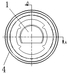
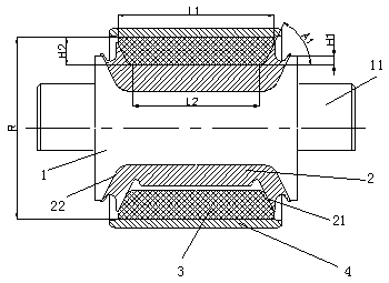
[0041] like Figure 1-Figure 3 As shown, a split casing 3-axle box positioning node includes a mandrel 1, a rubber layer 2, a split casing 3, and an overall casing 4. The rubber layer 2 is vulcanized and bonded on the outside of the mandrel 1, and the split casing 3 is set On the outside of the rubber layer 2, the overall jacket 4 is arranged on the outside of the split jacket 3; wherein the split jacket 3 is a circular sleeve that is divided into multiple pieces and has the same specifications in pairs, and includes a main body 1 31 positioned on the outside and a 31 positioned on the inside. Main body 2 32, main body 1 31 is a hollow cylinder inside, main body 2 32 is a circular cylinder with internal hollow and concave slopes at both ends, the outer side of main body 2 32 and the inner side of main body 1 31 are connected as a whole .

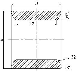
[0042] like figure 2 and image 3 As shown, the thickness H2 of the split coat 3, the length L1 of the split coat 3 main body one 31, t...

Embodiment 2

[0053] This embodiment is basically the same as Embodiment 1, the difference is that: Figure 4 and 5 As shown, between the thickness H2 of the split coat 3, the length L1 of the split coat 3 main body one 31, the length L2 of the split coat 3 main body two 32 inner sides and the inclined plane and the inner side of the split coat 3 main body two 32 two ends The relationship between the angle A1 is: H2≤[(L1-L2) / 2]*tanA1, the length of the outer surface of the main body two 32 of the split coat 3 is less than the length of the main body one 31 of the split coat 3, and the two ends of the main body one 31 There is a protruding end protruding relative to the main body 2 32. At this time, the thickness H3 of the main body 1 31 of the split casing 3 is not less than 3 mm, so as to ensure the strength of the protruding end when the axle box positioning node is loaded, and avoid deformation of the protruding end .

[0054] Specifically, the length L2 of the inner side of the main b...


PUM

PropertyMeasurementUnit
Thicknessaaaaaaaaaa

Abstract

The invention discloses a method for adjusting the rigidity of an axle box positioning node with sectioning jackets and the axle box positioning node. The axle box positioning node is arranged into the structure that rubber layers are arranged on the outer side of a mandrel, the sectioning jackets are arranged on the outer sides of the rubber layers and an integral jacket is arranged on the outersides of the sectioning jackets, wherein the sectioning jackets are divided into a plurality of circular sleeves with same specifications in pairs, and comprises a main body I positioned on the outerside and a main body II positioned on the inner side, the main body I is an internally hollow cylinder, the main body II is an internally hollow cylinder with concave inclined surfaces at two ends, and the outer side of the main body II is connected with the inner side of the main body I to form an integral body; and different rigidity values of the axle box positioning node in all directions areadjusted by adjusting the value of each parameter of the sectioning jackets so as to meet different rigidity requirements of different types of vehicles on the axle box positioning node in all directions. The sectioning jackets are arranged into a plurality of combined blocks, so that the inner side faces of the cylinders of the sectioning jackets can be lower than the outer side faces at two H-shaped ends of the mandrel, and the adjustable range of the rigidity of the axle box positioning node is preferably enlarged.

Description

technical field [0001] The invention relates to a stiffness adjustment method and structure of an axle box positioning node, in particular to a stiffness adjustment method of a split outer outer axle box positioning node and the axle box positioning node, belonging to the technical field of rail vehicle component manufacturing. Background technique [0002] The axle box structure is the movable joint connecting the frame and the wheel set on the rail vehicle. In addition to transmitting forces and vibrations in various directions, the axle box structure must also ensure that the wheel set can jump up and down and move side to side relative to the frame to adapt to the track conditions. Axle box positioning is also wheel set positioning, that is, restricting the mutual position between the wheel set axle box and the frame. The load is transmitted and distributed to the wheelset; the wheelset rotates flexibly, and the bogie passes the curve smoothly; the stable inertia of the ...

Claims


Application Information

Patent Timeline
IPC IPC(8): B61F5/30
CPCB61F5/305
Inventor 陈俊辉黄江彪雷军玉曾先会肖祥龙曾慧
Owner ZHUZHOU TIMES RUIWEI ANTI VIBERATION EQUIP LTD
Why Eureka
Try Eureka