Machine for efficient winding after blow molding of film

A film blowing and rewinding technology, which is applied in the direction of winding strips, thin material processing, transportation and packaging, can solve the problems of low winding efficiency of the rewinding machine and the inability to adjust the film width and size, and achieves a high level of improvement. The effect of winding efficiency

Inactive Publication Date: 2018-02-23
陈沉
View PDF1 Cites 0 Cited by
  • Summary
  • Abstract
  • Description
  • Claims
  • Application Information

AI Technical Summary

Problems solved by technology

[0002] The production of plastic films mainly includes various methods such as blow molding, stretch molding, and salivation molding. Among them, blow molding is to make the molten material plasticized by the barrel of the extruder, and make a cylindrical film blank through a molding die to extrude. , and then blow air with a certain pressure into the cylinder to inflate the cylindrical film blank plastic to reach the diameter and thickness of the film cylinder required for production. After cooling and shaping into a film product, it will be a finished product after cutting and winding. The winding efficiency of the winding machine used is not high. For example, the patent application publication number 201521132076.6 discloses a high-efficiency winding machine after film blow molding, including a frame and a trimming device. Both sides of the frame are equipped with winding The winding device includes a driving roller connected to a torque motor. One side of the driving roller is provided with a winding pressure roller connected to the winding cylinder, and the other side is provided with a hypotenuse, and a winding roller is mounted on the hypotenuse. The winding roller Pressing down on the driving roller, it also includes a controller connected to the torque motor. The controller is connected to the torque adjustment knob and the torque display. However, during the use of the above patents, it cannot be adjusted according to the width of the film, and it cannot be avoided. Relative slip between the film and the take-up drum

Method used


Image

  • Machine for efficient winding after blow molding of film
  • Machine for efficient winding after blow molding of film
  • Machine for efficient winding after blow molding of film

Examples


Embodiment Construction

[0020] The following will clearly and completely describe the technical solutions in the embodiments of the present invention with reference to the accompanying drawings in the embodiments of the present invention. Obviously, the described embodiments are only some, not all, embodiments of the present invention. Based on the embodiments of the present invention, all other embodiments obtained by persons of ordinary skill in the art without making creative efforts belong to the protection scope of the present invention.

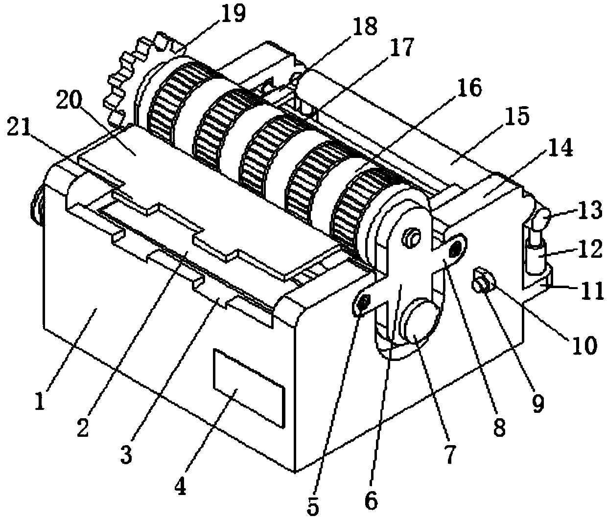
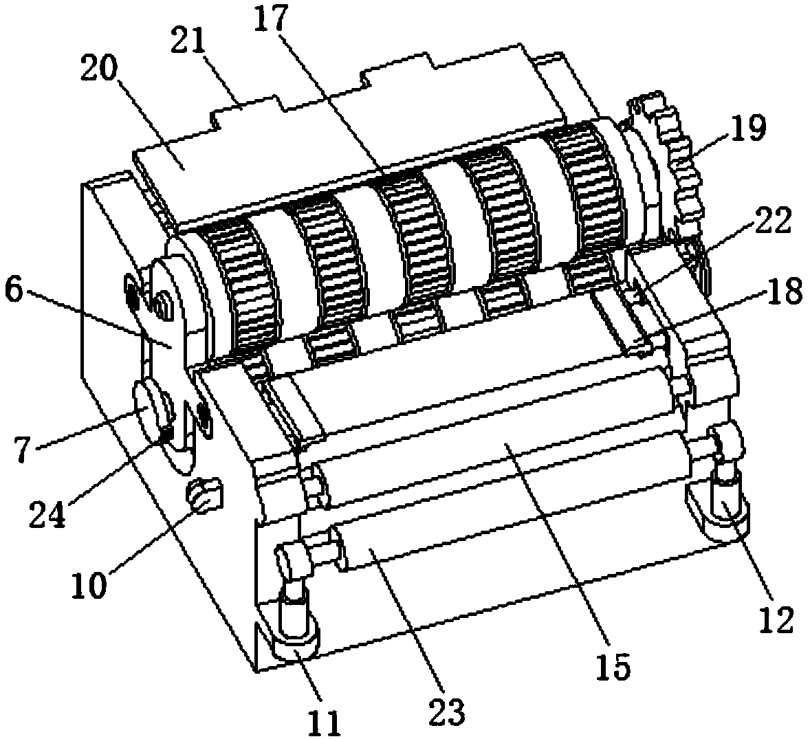
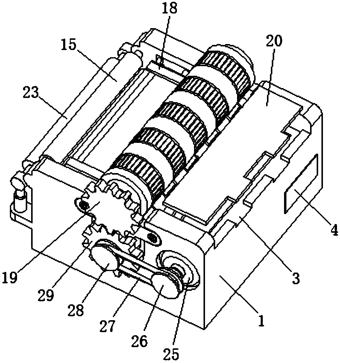
[0021] see Figure 1-3 , the present invention provides a technical solution: a high-efficiency winder after film blow molding, including a base 1, the upper side of the base 1 is provided with a through groove, and two sets of winding rollers 16 are arranged inside the through groove for For the transmission and feeding of the film, the outside of the winding drum 16 is equipped with equidistant anti-skid rings 17 to prevent the relative sliding of the film a...


PUM


Abstract

The invention discloses a high-efficiency winder after film blow molding, which includes a base, a through groove is arranged on the upper side of the base, one end of the rotating shaft passes through a coupling plate and is respectively connected with a first gear and a second gear. gear, the end of the rotating shaft close to the second gear is provided with a second V-belt pulley, the first gear and the second gear are meshed, and the base is provided with two symmetrically distributed guards on both sides of the winding drum. The upper side of the base is provided with a rectangular through groove, and the L-shaped pressing plate connected by the telescopic push of the second electric telescopic rod can be adjusted according to the width of the film. The anti-skid ring provided on the outside of the winding drum can prevent the film from In the case of relative sliding between the winding rollers, the meshing transmission of the first gear and the second gear drives the relative rotation between the winding rollers, which can improve the winding efficiency.

Description

technical field [0001] The invention relates to the technical field of winding machine equipment, in particular to a high-efficiency winding machine after film blow molding. Background technique [0002] The production of plastic films mainly includes various methods such as blow molding, stretch molding, and salivation molding. Among them, blow molding is to make the molten material plasticized by the barrel of the extruder, and make a cylindrical film blank through a molding die to extrude. , and then blow air with a certain pressure into the cylinder to inflate the cylindrical film blank plastic to reach the diameter and thickness of the film cylinder required for production. After cooling and shaping into a film product, it will be a finished product after cutting and winding. The winding efficiency of the winding machine used is not high. For example, the patent application publication number 201521132076.6 discloses a high-efficiency winding machine after film blow mol...

Claims


Application Information

Patent Timeline
Patent Type & Authority Applications(China)
IPC IPC(8): B65H18/10B65H23/26B65H75/26
CPCB65H18/10B65H23/26B65H75/26B65H2701/1924
Inventor 陈沉
Owner 陈沉
Why Eureka
Try Eureka