Piling machine

A technology of pile driver and base plate, applied in sheet pile wall, construction, infrastructure engineering and other directions, can solve the problems of complicated operation and poor stability of pile body, and achieve the effect of improving positioning accuracy and efficiency

Pending Publication Date: 2018-02-23
TONGXIANG TIANSHUN MOLD CO LTD
View PDF4 Cites 1 Cited by
  • Summary
  • Abstract
  • Description
  • Claims
  • Application Information

AI Technical Summary

Problems solved by technology

However, the operation of such equipment is complicated. After the soil extraction is completed, the hole for soil extraction ...

Method used


Image

  • Piling machine
  • Piling machine

Examples


Embodiment 1

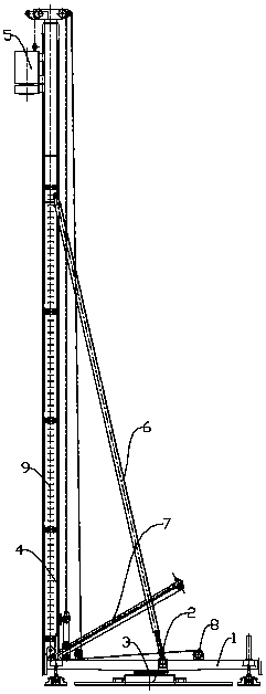
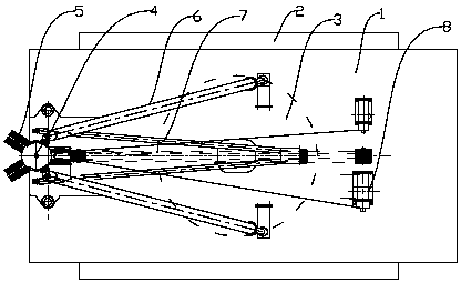
[0012] Such as figure 1 , figure 2 As shown, a pile driver described in this embodiment includes a base 2 for positional movement and a base plate 1 arranged on the base 2, a rotating shaft 3 is arranged at the center of the base 2, and the base plate 1 is rotated The shaft 3 is rotationally connected with the base 2; a drill frame 4 is arranged at one end of the base plate 1, two power heads 5 are arranged at the upper end of the drill frame 4, and corresponding The slide rail 9, the slide rail 9 is used to guide the drill rod installed on the power head 5 in the vertical direction; the landing gear 7 is arranged at the joint between the drill rod and the base plate 1, and the other end opposite to the drill stand 4 Two winches 8 are arranged on the base plate 1; the two winches 8 are respectively connected with the two power heads 5 through wire ropes and the landing gear 7; an inclined support rod 6 is set between the drill frame 4 and the base plate 1; The centers of th...


PUM


Abstract

The invention relates to the field of piling equipment, in particular to a piling machine. The piling machine comprises a base and a base board arranged on the base; a rotary shaft is arranged in thecenter of the base; the base board is rotationally connected with the base through the rotary shaft; one end of the base board is provided with a drilling frame; two power heads are arranged at the upper end of the drilling frame; a drill stem below each power head is provided with a corresponding slide rail; two winches are arranged at the position, at the other end opposite to the drilling frame, of the base board; and the centers of the two drill stems installed on the two power heads are separately located on the same circumference with the center of the rotary shaft as the circle center.According to the piling machine, the two power heads are arranged on the drilling frame, at the same time, through the reasonable position design of the power heads, the effect that only the base board needs to rotate on the rotary shaft by a certain angle in the switching process of soil sampling and piling is achieved, the soil sampling and piling positioning precision can be greatly improved, simpleness and convenience are achieved, and efficiency is improved.

Description

technical field [0001] The invention relates to the field of pile driving equipment, in particular to a pile driver. Background technique [0002] In the prior art, two drill frames are used on the pile driver, and a power head is respectively installed on the two drill frames, which are assembled on the power head, and soil fetching and piling operations are respectively carried out after the assembly. However, such equipment is complicated to operate, and after the soil fetching is completed, the hole for the soil fetching needs to be positioned and then the piling operation is carried out. If there is a certain deviation, defects such as poor stability of the pile body will be caused. Contents of the invention [0003] The purpose of the present invention is to provide a pile driver with simple structure, convenient piling operation and high efficiency in order to solve the above technical deficiencies. [0004] In order to achieve the above object, a pile driver desig...

Claims


Application Information

Patent Timeline
IPC IPC(8): E02D7/06E02D13/04
CPCE02D7/06E02D13/04
Inventor 杨炎林浦晓锋
Owner TONGXIANG TIANSHUN MOLD CO LTD
Why Eureka
Try Eureka