Adhesive-free testing device and method for rock direct tensile test

A technology of tensile test and test device, which is applied in the direction of measuring device, using stable tension/pressure test material strength, instruments, etc., can solve problems such as uneven adhesive thickness, insufficient bonding strength, and test failure. Achieve the effect of avoiding bonding fracture, easy operation and low requirements

Pending Publication Date: 2018-02-23
ARMY ENG UNIV OF PLA
View PDF1 Cites 11 Cited by
  • Summary
  • Abstract
  • Description
  • Claims
  • Application Information

AI Technical Summary

Problems solved by technology

[0005] The technical problem to be solved by the present invention is to overcome the shortcomings of the prior art and provide a non-adhesive test device and method for direct tensile tests on rocks. When the connection test is carried out in the connection mode, the defect of test failure is usually caused by insufficient bonding strength, uneven thickness of the adhesive, or peeling of the end; It needs to be bonded with high-strength g

Method used


Image

  • Adhesive-free testing device and method for rock direct tensile test
  • Adhesive-free testing device and method for rock direct tensile test
  • Adhesive-free testing device and method for rock direct tensile test

Examples


Embodiment 1

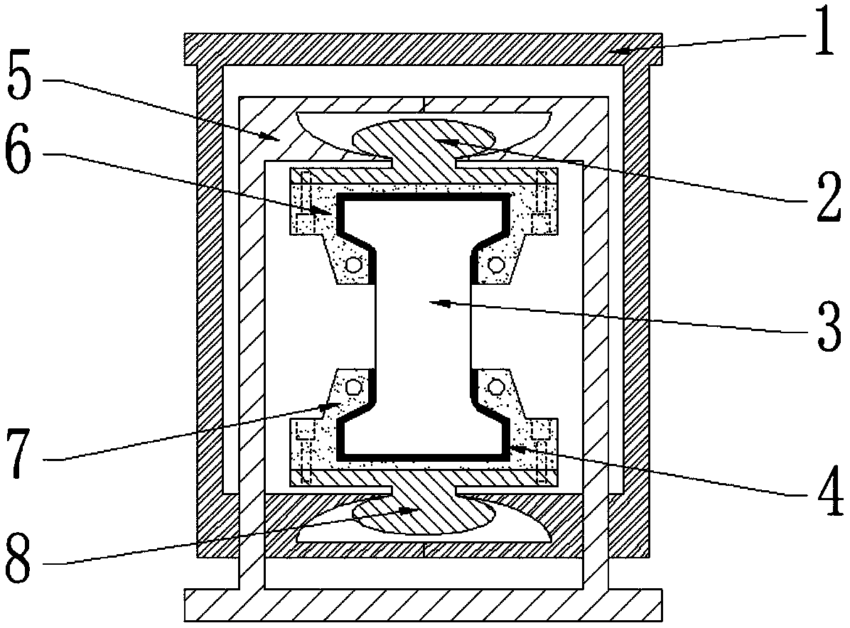
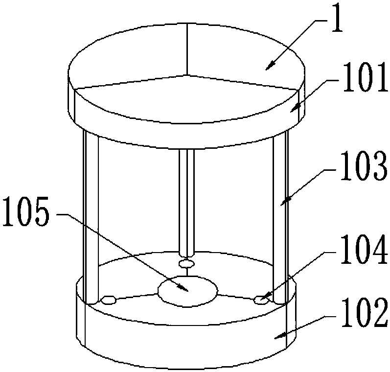
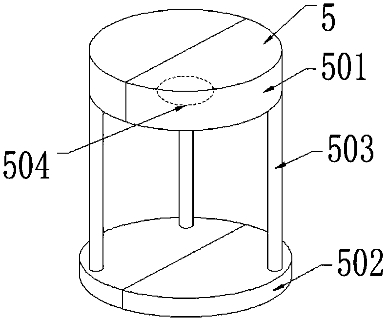
[0031] This embodiment provides a stick-free test device for direct tensile test of rock, such as figure 1 shown, including the outer bracket 1 and the inner bracket 5, such as figure 2 As shown, the outer bracket 1 and the inner bracket 5 are sleeved together with the inner bracket column 503 through the inner bracket column mounting holes 104. The outer bracket 1 includes an outer bracket upper plate 101 and an outer bracket lower plate 102 arranged in parallel, and the outer bracket upper plate 102. Between 101 and the lower plate 102 of the outer bracket, the upper and lower plates of the outer bracket are installed with outer bracket pillars 103, the lower plate 102 of the outer bracket is provided with the mounting hole 104 of the inner bracket pillar, and the center position of the upper surface of the lower plate 102 of the outer bracket is There is a pull-down head mounting hole 105; such as image 3 As shown, the inner bracket 5 includes an inner bracket upper plat...

Embodiment 2

[0034] The present embodiment provides a non-stick test method for direct tensile test of rock, including the following specific steps:

[0035] (1) An incompletely closed ellipsoid pull-down head installation hole 105 is reserved at the center of the lower plate 102 of the outer bracket, and the fixing part of the pull-down head 8 is installed in it, and the upper pull-down head 2 is installed in the inner bracket in the same way Inside the incompletely closed ellipsoid upper slider mounting hole 504 at the inner center position of the upper plate 501; then the outer bracket upper plate 101 and the outer bracket lower plate 102 are welded and combined into a whole by the outer bracket struts 103; the inner bracket struts 503 passes through the mounting holes 104 of the inner support struts on the outer support lower plate 102, and then the inner support upper plate 501 and the inner support lower plate 502 are welded and assembled into the inner support 5 through the inner sup...


PUM


Abstract

The invention provides an adhesive-free testing device and method for a rock direct tensile test. The adhesive-free testing device comprises an external support and an internal support, wherein the external support and the internal support are sheathed together through an internal support strut mounting hole and an internal support strut; the invention further provides an adhesive-free testing method for rock direct tensile test; the defects that by using the existing experimental method and due to strong rock crispiness, the connection test is fail by adopting the adhesion manner due to pooradhesion intensity, uneven adhesive thickness or end falling; a crispy material test piece is fixedly arranged through an upper base and a lower base without the need of high-intensity adhesive adhesion, in application of pressure, the internal support and an upper pull head are fixed, the external support moves downward to drive a lower pull head to directly stretching the crispy material test piece, thus facilitating observation; during stretching process, the upper pull head and the lower pull head can eliminate the eccentricity of the test piece through small-amplitude rotation during stretching process; therefore, pressure can be converted into pull, thus realizing the direct tensile of the crispy material test piece such as rock and the like.

Description

technical field [0001] The invention belongs to the field of rock mechanics or material testing, and in particular relates to a stick-free pressure-pull conversion device suitable for direct tensile test of brittle material test pieces (rock, concrete, etc.) and a corresponding test method. Background technique [0002] Rock and concrete are common materials in infrastructure construction. Both of these two types of materials have good compressive properties, but they are brittle and low in tensile strength. Therefore, accurate determination of the tensile strength of these materials is extremely important for rationally determining design parameters and avoiding brittle and catastrophic failure of engineering structures. important role. [0003] At present, there are two main types of test methods for determining the tensile strength of rocks: indirect methods and direct methods. The indirect method is to obtain the tensile strength of the tested material indirectly throu...

Claims


Application Information

Patent Timeline
IPC IPC(8): G01N3/08G01N3/04
CPCG01N3/04G01N3/08G01N2203/0017G01N2203/0423G01N2203/0435G01N2203/0268
Inventor 范鹏贤刘一鸣王明洋王德荣李杰马林建方向
Owner ARMY ENG UNIV OF PLA
Why Eureka
Try Eureka