
Die ejector

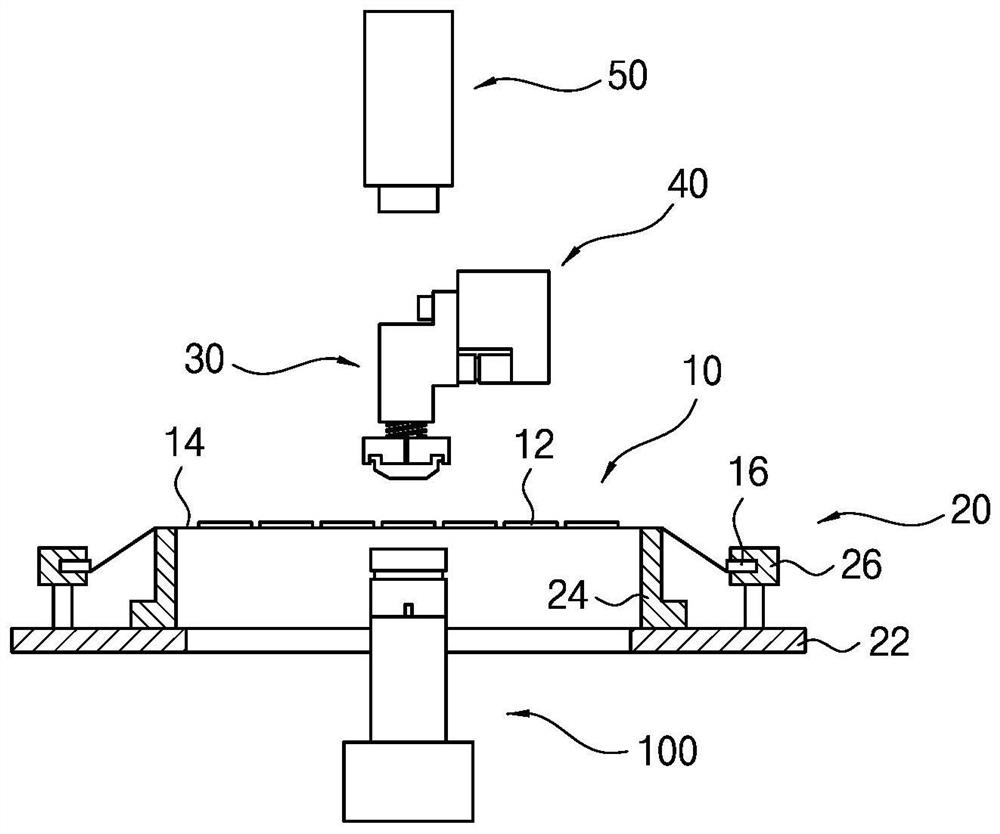
A technology for ejecting devices and bare cores, which is used in transportation and packaging, semiconductor devices, electrical components, etc., and can solve problems such as the size and shape of bare cores.

Active Publication Date: 2021-08-13
SEMES CO LTD
View PDF4 Cites 0 Cited by
  • Summary
  • Abstract
  • Description
  • Claims
  • Application Information

AI Technical Summary

Problems solved by technology

However, there is a mechanical limit to reducing the pitch of the vias, and therefore it is difficult to aggressively deal with the size and shape of the die

Method used


Image

  • Die ejector
  • Die ejector
  • Die ejector

Examples


Embodiment Construction

[0028] Hereinafter, embodiments of the present invention will be described with reference to the drawings. However, the invention is not limited to the embodiments described below and can be implemented in various forms. The provision of the following examples is not intended to complete the present invention but inteaccomifically convey the scope of the invention to those skilled in the art.

[0029] In the specification, when an element is referred to as above or connected to another element or layer, it can be directly located above or connected to another element or layer, or may There is an intermediate element or layer. In fact, it is understood that when a component is called directly on another element or layer or directly to another element or layer, it means there is no intermediate element. Likewise, although the terms such as first, second, and third, the terms are used to describe each of the regions or layers of the embodiments of the present invention, the region or...


PUM


Abstract

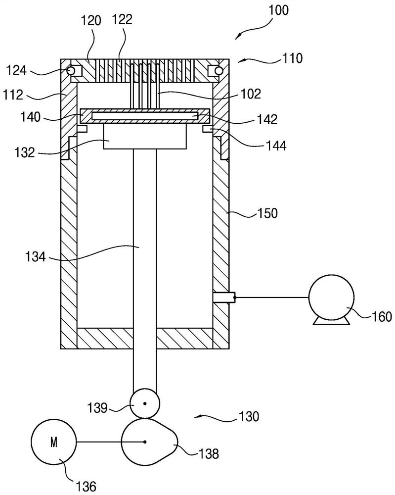
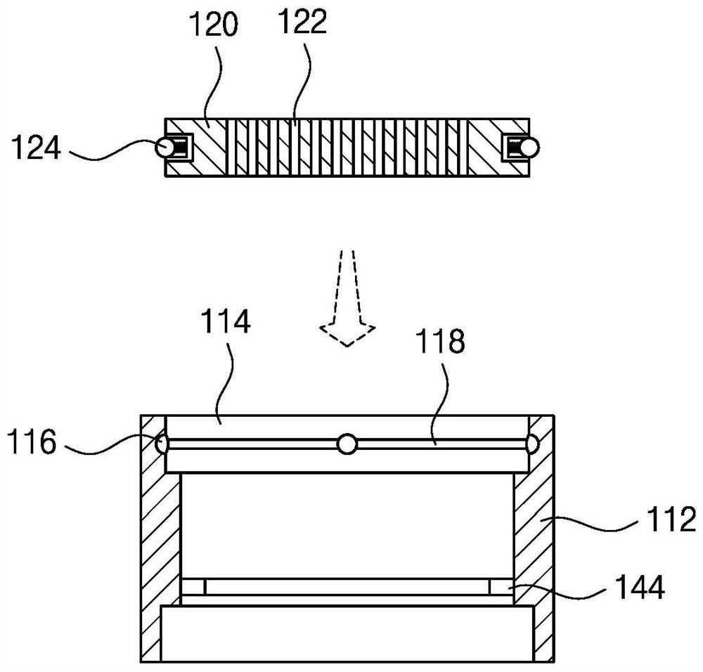
A bare core ejector includes a cylindrical case, a disc-shaped cover rotatably mounted on an upper portion of the case and having a plurality of through holes, an ejector pin inserted into a part of the through holes and used to separate a bare core from a dicing tape and a drive that moves the ejector pin vertically to separate the die from the dicing tape. In particular, the through holes are arranged in multiple rows and columns, and the centers of the through holes are separated from the center of the cover by a predetermined distance.

Description

[0001] technical background [0002] The present invention relates to a naked core outlet device. More specifically, the present invention relates to a naked core for separating a bare core from the cutting strip of the fax wafer in the bare core engagement process, wherein the bare core is bonded to such as a lead frame. And on a substrate such as a printed circuit board. [0003] Typically, the semiconductor device can be formed by the silicon wafer as a semiconductor substrate by repeating a series of preparation processes. The semiconductor device formed by the manner as described above can be cut by a cutting process and can be bonded to a substrate by a bare core adhesive process. [0004] The device for performing a bare core adhesive process can include picking up the module and the bonding module, and the pickup module is used to pick up the naked core from the bone core including a naked core through the cutting process, and the bonding module is used for Bonding the bare ...

Claims


Application Information

Patent Timeline
Patent Type & Authority Patents(China)
IPC IPC(8): H01L21/677H01L21/683
CPCH01L21/67703H01L21/683H01L2221/67H01L2221/683H01L21/67712H01L21/67721H01L21/6836H01L21/68742
Inventor 李喜澈崔一洛李在卿
Owner SEMES CO LTD
Learn More