Method for joining components and component composite

A composite structure and component technology, applied in the direction of connecting components, thin plate connections, welding equipment, etc., can solve the problems of shock absorption at bad joints, excessive weight increase of component composite structures, and high cost, and achieve low-cost load capacity and improve load capacity. , Simplify the effect of relative alignment

Active Publication Date: 2018-02-23
BAYERISCHE MOTOREN WERKE AG
View PDF6 Cites 1 Cited by
  • Summary
  • Abstract
  • Description
  • Claims
  • Application Information

AI Technical Summary

Problems solved by technology

The disadvantage of this connection is that the connection of the functional element to the first component has a relatively poor load capacity and poor vibration damping of the joint
Furthermore, feeding functional elements by pressing in is complex and expensive
In addition, such solutions often add excessive weight to the component composite structure

Method used


Image

  • Method for joining components and component composite
  • Method for joining components and component composite
  • Method for joining components and component composite

Examples


Embodiment Construction

[0045] Components with the same function and mode of action are each provided with the same reference symbols in FIGS. 1 to 8 .

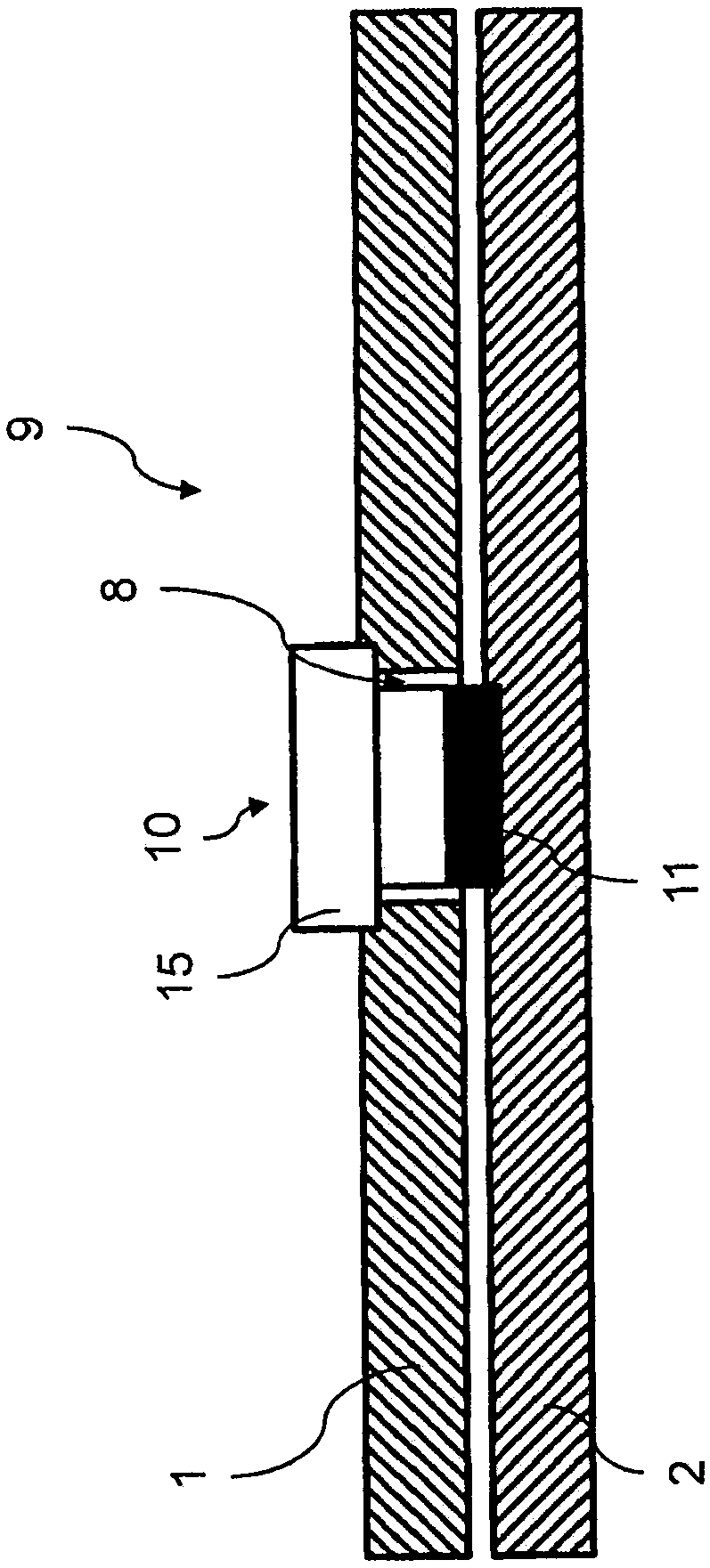
[0046] FIG. 1 schematically shows a first component assembly 9 according to the prior art. The first component 1 and the second component 2 are arranged opposite each other in the connected position. A screw 10 with a screw head 15 is pressed into the first penetration 8 of the first component 1 . The screw head 15 rests on the surface of the first component 1 and thus prevents the screw 10 from moving further into the first passage 8 . The side of the screw 10 remote from the screw head 15 is connected to the second component 2 via a weld seam 11 .

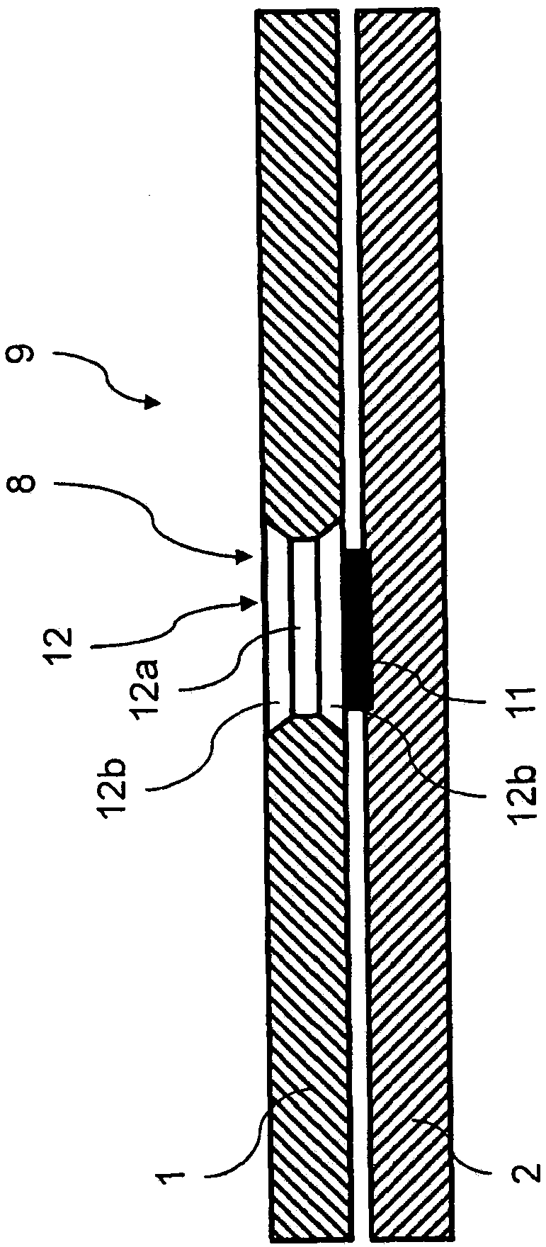
[0047] FIG. 2 schematically shows a second component assembly 9 according to the prior art. The first component 1 and the second component 2 are arranged opposite each other in the connected position. Into the first passage 8 of the first component 1 is pressed an insert 12 which has a cylindrical ...


PUM


Abstract

The invention discloses a method for joining components and a component composite. The invention relates to a method for joining a first component (1) to a second component (2), comprising the following steps: a first component (1) with a first joining part receiving section (3) is provided; a joining part (4) is produced on and / or in the first joining part receiving section (3) by means of a generative method; a second component (2) with a second joining part receiving section (5) is provided; and the joining part (4) is joined to the second joining part receiving section (5) of the second component (2). The invention also relates to a component composite which is produced by means of the claimed method.

Description

technical field [0001] The invention relates to a method for connecting a first component and a second component by means of a joint and to a component composite structure produced by means of the method according to the invention. Background technique [0002] Various joining methods are known for connecting two components, such as screwing, riveting, gluing, soldering, welding or clamping. Body components, which may be of different materials, such as steel, aluminum or fiber-reinforced plastics, such as carbon-fiber-reinforced plastics (CFK), aramid-fiber-reinforced plastics (AFK) or glass-fiber-reinforced plastics (GFK), are used in body production. The body components are connected to one another, for example, by means of blind riveting, punch riveting, adhesive bonding or other joining techniques. The disadvantage of these methods is that the joints produced generally have a relatively poor load capacity and poor joint damping, which can have a negative effect on the v...

Claims


Application Information

Patent Timeline
Patent Type & Authority Applications(China)
IPC IPC(8): F16B5/08
CPCB33Y80/00B29C65/48B29C65/56B29C65/564B29C65/565B29C66/1122B29C66/21B29C66/41B29C66/721B29C65/02F16B5/08B29C66/7212B29K2307/04B29K2277/10B29K2309/08B23K26/21B23K26/354B23K1/19B23K26/34
Inventor B·格吕克R·基施纳U·施密德
Owner BAYERISCHE MOTOREN WERKE AG
Why Eureka
Try Eureka