Continuous heat treatment furnace and method for manufacturing ceramic electronic components using the continuous heat treatment furnace

A technology for heat treatment of furnaces and workpieces, applied in capacitor manufacturing, furnace components, electrical components, etc., can solve the problems of workpiece W quality deviation, uneven degreasing results, etc., and achieve the effect of uniform heat treatment

Active Publication Date: 2020-03-10
MURATA MFG CO LTD
View PDF4 Cites 0 Cited by
  • Summary
  • Abstract
  • Description
  • Claims
  • Application Information

AI Technical Summary

Problems solved by technology

As a result, the degreasing result becomes uneven, which may lead to quality deviation of the workpiece W

Method used


Image

  • Continuous heat treatment furnace and method for manufacturing ceramic electronic components using the continuous heat treatment furnace
  • Continuous heat treatment furnace and method for manufacturing ceramic electronic components using the continuous heat treatment furnace
  • Continuous heat treatment furnace and method for manufacturing ceramic electronic components using the continuous heat treatment furnace

Examples


Embodiment approach 1

[0042] - Embodiment 1 of continuous heat treatment furnace -

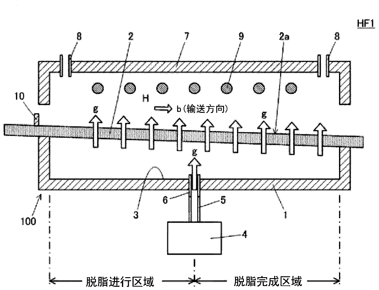
[0043] use Figure 1 ~ Figure 3 , the continuous heat treatment furnace HF1 which is Embodiment 1 of the continuous heat treatment furnace according to the present invention will be described. Continuous heat treatment furnace HF1 is a degreasing furnace for degreasing non-degreasing ceramic electronic components. Next, an embodiment of the continuous heat treatment furnace according to the present invention will be described by taking the above-mentioned degreasing furnace as a specific example.

[0044]

[0045] figure 1 It is a cross-sectional view schematically showing the continuous heat treatment furnace HF1. The continuous heat treatment furnace HF1 is provided with a heat treatment region H for heat-treating the workpiece along the conveyance direction b of the workpiece (not shown). The workpiece is heat-treated while being conveyed in the heat-treatment area H. As shown in FIG. The workpiece, as d...

example 2

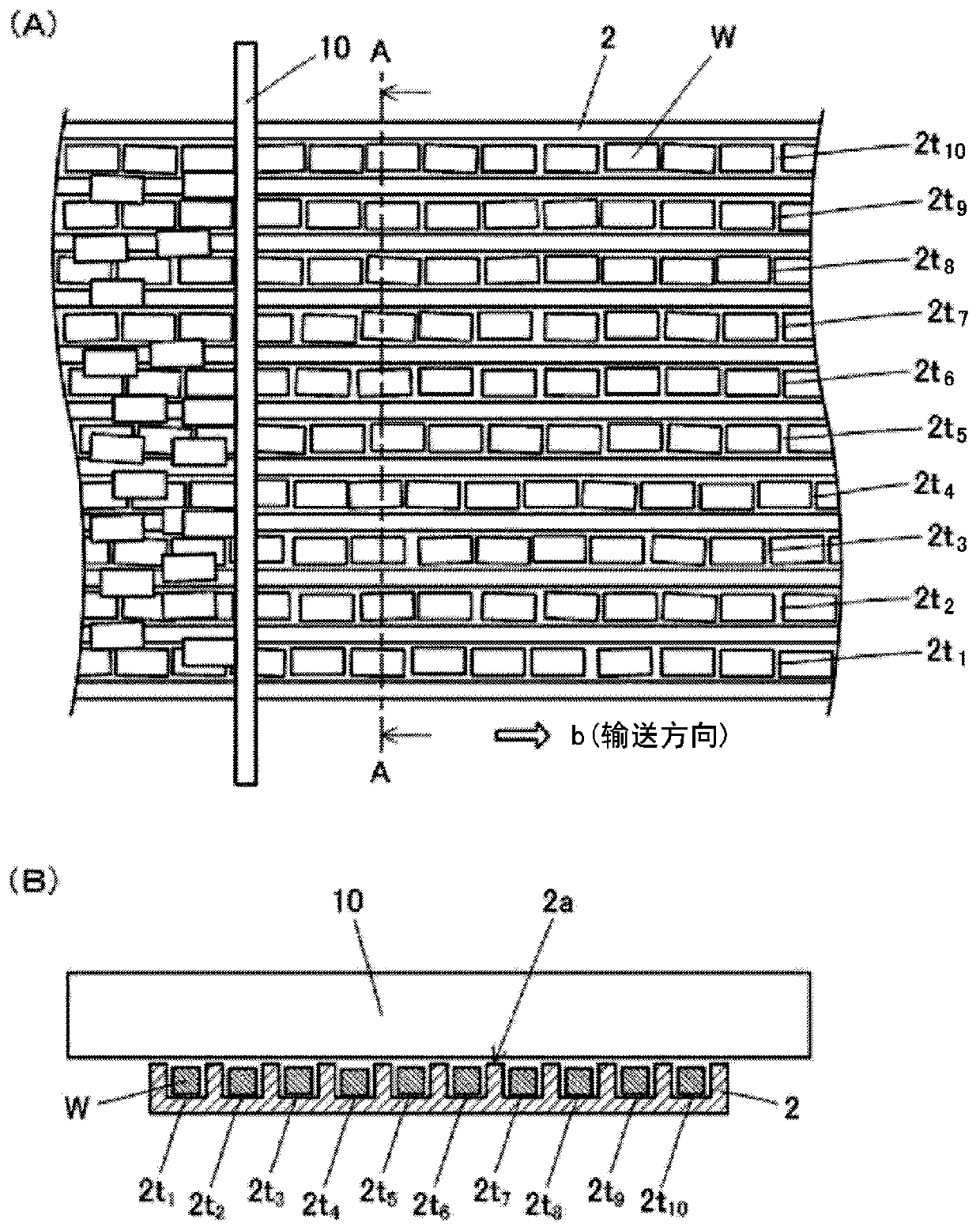
[0067] Figure 5 is the equivalent of the porous plate 2B, which is Modification 2 of the porous plate 2 included in the workpiece conveying mechanism 100. figure 2 (B) A cross-sectional view in the direction of the arrow. In the porous plate 2B, the groove 2t formed in the upper surface 2Ba 1 ~2t 10 The cross-section perpendicular to the conveying direction b of the workpiece W is V-shaped.

[0068] In this case, as in the porous plate 2A, the workpiece W and the groove 2t 1 ~2t 10 There is a gap between the bottoms, so that it is easy to supply gas g from the bottom. Furthermore, since the area of ​​the opening of the upper surface 2Ba becomes larger, the supplied gas g flows more easily. Therefore, the binder contained in the workpiece W can be burned more efficiently, and the heat generated by burning the binder can be dissipated more effectively.

[0069]

[0070] Image 6is the equivalent of the porous plate 2C, which is Modification 3 of the porous plate 2 in...

Embodiment approach 2

[0072] - Embodiment 2 of continuous heat treatment furnace -

[0073] use Figure 7 and Figure 8 , the continuous heat treatment furnace HF2 which is Embodiment 2 of the continuous heat treatment furnace according to the present invention will be described. The continuous heat treatment furnace HF2 is a degreasing furnace for degreasing an electronic component body constituting a ceramic electronic component, similarly to the continuous heat treatment furnace HF1.

[0074] Figure 7 It is a cross-sectional view schematically showing the continuous heat treatment furnace HF2. The gas chamber of the continuous heat treatment furnace HF2 is divided into a first gas chamber 3a and a second gas chamber 3b. The air supply unit 4 communicates with the first air chamber 3a via the first pipe 5a and the first air supply port 6a, and communicates with the second air chamber 3b via the second pipe 5b and the second air supply port 6b, to Gas g is provided in each gas chamber. The ...


PUM


Abstract

In this continuous heat treatment furnace (HF1), a heat treatment region in which heat treatment is performed on a workpiece along a conveyance direction (b) is provided. The workpiece is subjected to heat treatment while being conveyed in the heat treatment region (H). A workpiece conveyance mechanism (100) for conveying the workpiece is provided with: a box-shaped base frame (1) having an opening section in the upper part thereof; a porous plate (2); a gas chamber (3) that is formed by the porous plate (2) covering the opening section of the base plate (1); and a gas supply means (4) that is connected to the gas chamber (3) and that supplies, to the gas chamber (3), gas (g) to penetrate through the porous plate (2) to flow out. The porous plate (2) is arranged such that the upper surface (2a) thereof is downwardly inclined in the conveyance direction for the workpiece, and grooves (2t1 to 2t10) along the conveyance direction for the workpiece (W) are formed in the upper surface (2a).

Description

technical field [0001] The present invention relates to a continuous heat treatment furnace provided with a workpiece conveyance mechanism for conveying a plurality of minute workpieces (objects to be processed), and a method of manufacturing ceramic electronic components using the continuous heat treatment furnace. Background technique [0002] Continuous processing equipment includes a workpiece transport mechanism for continuously transporting workpieces. As such workpiece conveyance mechanisms, belt conveyors, roller conveyors, and the like are widely used. However, in the above-mentioned workpiece conveying mechanism, it is necessary to provide a driving mechanism for driving the conveyor belt and the roller, which makes the workpiece conveying mechanism complicated and large, resulting in an increase in the cost of manufacturing the workpiece conveying mechanism. [0003] Therefore, it is necessary to simplify the structure of the workpiece conveyance mechanism. An e...

Claims


Application Information

Patent Timeline
Patent Type & Authority Patents(China)
IPC IPC(8): F27B9/20F27B9/24F27D3/12H01G4/12H01G4/30H01G13/00
CPCF27B9/20F27B9/24F27D3/12H01G4/12H01G4/30H01G13/00F27B9/3077
Inventor 则冈铁人中谷行宏高畑猛
Owner MURATA MFG CO LTD
Why Eureka
Try Eureka