Mechanical arm gravity compensated cam tension spring mechanism

A technology of gravity compensation and mechanical arm, which is applied in the field of cam tension spring mechanism for gravity compensation of mechanical arm, can solve the problems of increased cost and overall structural size of the mechanical arm, and achieves a small space occupation, compact structure and simple structure. Effect

Inactive Publication Date: 2018-02-27
UNIV OF SHANGHAI FOR SCI & TECH
View PDF5 Cites 20 Cited by
  • Summary
  • Abstract
  • Description
  • Claims
  • Application Information

AI Technical Summary

Problems solved by technology

In theory, the active gravity compensation device can realize the complete gravity balance of the multi-joint manipulator, but it needs to compile complex control programs and algorithms, as well as real-time detection of the position and center of gravity of the manipulator
At the same time, due to the addition of motors, the overall structural size of the manipulator increases, and the cost increases accordingly.

Method used


Image

  • Mechanical arm gravity compensated cam tension spring mechanism

Examples


Embodiment 1

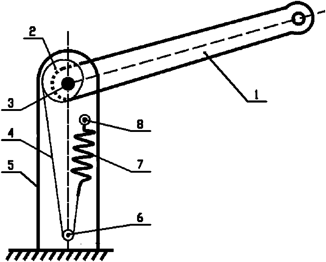
[0027] A cam tension spring mechanism for gravity compensation of a mechanical arm, its structure is as follows figure 1 As shown, it includes a mechanical upper arm 1, a mechanical lower arm 5, a disc cam 2, a pulley 6, a fixed pin 8, a wire rope 4 and an extension spring unit, and the mechanical upper arm 1 is arranged on the upper part of the mechanical lower arm 5 through joint hinge 3 rotation, and can be Rotate around the rotation center of the joint hinge 3, the disc cam 2 is fixedly connected with the mechanical upper arm 1, and rotates with the mechanical upper arm 1, after one end of the steel wire rope 4 is fixed with the disc cam 2, it is guided by the pulley 6 and then connected with the extension spring unit, Pulley 6 and the center of mechanical upper arm 1 rotating around mechanical lower arm 5 are located on the same vertical line, and extension spring 7 adopts fixed pin 8 fixedly connected with its end to be installed on mechanical lower arm 5 .

[0028] When...


PUM


Abstract

The invention relates to a mechanical arm gravity compensated cam tension spring mechanism. The mechanical arm gravity compensated cam tension spring mechanism comprises an upper mechanical arm (1), alower mechanical arm (5), a disk-shaped cam (2), a steel wire rope (4) and a tension spring unit. The upper mechanical arm (1) is rotationally arranged at the upper end of the lower mechanical arm (5). The disk-shaped cam (2) is fixedly connected with the upper mechanical arm (1). One end of the steel wire rope (4) is fixed to the edge of the disk-shaped cam (2), and the other end of the steel wire rope (4) is fixedly connected to the tension spring unit on the lower mechanical arm (5). Compared with the prior art, the mechanical arm gravity compensated cam tension spring mechanism has the beneficial effect that complete gravity compensation in a large rotation angle range of a mechanical arm joint can be achieved. The realization process of the mechanical arm gravity compensated cam tension spring mechanism is that the cam drives springs to deform so that the spring force can be correspondingly changed along with the movement of the mechanism, the changed gravitational potential energy of the mechanism arm is converted into elastic potential energy, and complete gravity balance effect of the mechanical arm joint within effective working space is achieved.

Description

technical field [0001] The invention relates to a mechanical device for gravity compensation of a mechanical arm, in particular to a cam extension spring mechanism for gravity compensation of a mechanical arm. Background technique [0002] Since the joints of the manipulator whose axis is parallel to the ground are affected by the gravity of the arm rod, additional torque will be generated at the joints, which will reduce the dynamic characteristics of the manipulator. Most manipulators need to design a gravity compensation device. The active gravity compensation mechanism generally adjusts the output torque of the motor, and then uses wire rope traction to offset the torque generated by the self-weight of the manipulator on the joints, thereby achieving the gravity balance of the manipulator. In theory, the active gravity compensation device can realize the complete gravity balance of the multi-joint manipulator, but it needs to compile complex control programs and algorith...

Claims


Application Information

Patent Timeline
Patent Type & Authority Applications(China)
IPC IPC(8): B25J19/00
CPCB25J19/0016
Inventor 崔建昆刘兵刘爽
Owner UNIV OF SHANGHAI FOR SCI & TECH
Why Eureka
Try Eureka