

Green ecological roof structure
A roof structure and ecological technology, applied in the direction of roof, roof cladding, building structure, etc., can solve the problems of insufficient resource utilization, etc., and achieve the effect of being suitable for popularization and use, complete and compact structure design, and reasonable design
- Summary
- Abstract
- Description
- Claims
- Application Information
AI Technical Summary
Problems solved by technology
Method used
Image

Examples
Embodiment Construction
[0018] The technical solutions in the embodiments of the present invention will be clearly and completely described below in conjunction with the accompanying drawings in the embodiments of the present invention. Obviously, the described embodiments are only some of the embodiments of the present invention, not all of them. Based on The embodiments of the present invention and all other embodiments obtained by persons of ordinary skill in the art without making creative efforts belong to the protection scope of the present invention.
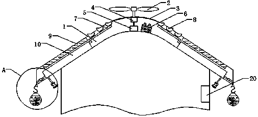
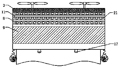
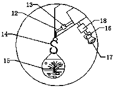
[0019] see Figure 1-4 , the present invention provides a technical solution: a green ecological roof structure, including a roof body 1, fan blades 2, flower pots 8, solar photovoltaic panels 9 and PLC controller 20, the roof body 1 is in an inverted V shape, and the roof body 1. The top is convex and arc-shaped. There is a wind wheel on the top of the roof body 1. The fan blade 2 is installed on the wind wheel. The wind wheel is connected to t...
PUM
 Abstract
Description
Claims
Application Information