Subway shielding door lock with improved manual unlocking structure

A technology for manual unlocking and shielded doors, which is applied to handle connections, door/window accessories, building structures, etc., can solve the problems of automatic unlocking and easy misoperation, and achieve the effect of simple structure and preventing accidental touch

Inactive Publication Date: 2018-02-27
成都佳欣诚信科技有限公司
View PDF1 Cites 6 Cited by
  • Summary
  • Abstract
  • Description
  • Claims
  • Application Information

AI Technical Summary

Problems solved by technology

[0003] The current screen door locks are automatically controlled by the system when the power is on. If the system fails or the power is cut off and other emergencies, it cannot be automatically unlocked; so the subway screen door must be equipped with a manual device for unlocking.
However, the existing manual unlocking devices can be unlocked by moving them directly. Although the unlocking is fast, it is easy to misuse and cause unnecessary troubles.

Method used


Image

  • Subway shielding door lock with improved manual unlocking structure
  • Subway shielding door lock with improved manual unlocking structure
  • Subway shielding door lock with improved manual unlocking structure

Examples


Embodiment 1

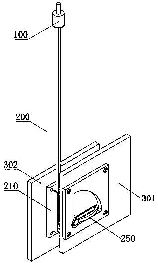
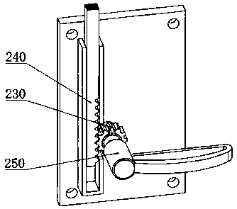
[0031] The present invention is realized in the following ways: as Figure 1-Figure 6 As shown, a subway screen door lock with an improved manual unlocking structure includes a lock body 100 that is vertically installed on the screen door and cooperates with the top box of the screen door to lock or unlock and a manual unlocking structure 200 connected to the lock body 100, The shielded door includes two A door panels 301 and B door panels 302 that are opposite and connected as one, and the lock body 100 is installed in the cavity formed by the A door panels 301 and B door panels 302; the manual unlocking structure 200 includes The support seat 210 fixedly installed on the inner wall of the B door panel 302 and the drive shaft 220, the wheel assembly 230, and the rack assembly 240 respectively installed on the support seat 210, the wheel assembly 230 driven by the drive shaft 220 and the drive shaft 230 installed on the lock body 100 The rack assembly 240 at the bottom end is ...

Embodiment 2

[0037]This embodiment is further optimized on the basis of the above-mentioned embodiments. The driving end of the handle 252 is provided with a limit protrusion; When the handle 252 is pulled out from the locking groove 2513 and rotated to the limit position along the unlocking groove 2512, the limiting block is in contact with the limiting protrusion, and at the same time, the rack assembly 240 moves down to a straight line The lowest end of the chute drives the lock body 100 to be completely unlocked through the manual unlocking structure 200 . In this embodiment, a limit protrusion and a limit hole are provided to add a limit guarantee, which can more effectively limit the rotation angle of the handle 252, unlock it quickly and accurately, and facilitate the return to the initial state later.

[0038] Other parts of this embodiment are the same as those of the foregoing embodiments, so details are not repeated here.

Embodiment 3

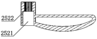
[0040] This embodiment is further optimized on the basis of the above embodiments, the length of the through hole 2521 is greater than the length of the inner spline groove 2522, and the end of the through hole 2521 without the inner spline groove 2522 is a smooth wall; the drive shaft 220 and The end connected to the driving end of the handle 252 is fixedly connected to the limit disk, and the linear movement range of the driving end of the handle 252 along the axis of the drive shaft 220 is limited within the length range of the external spline.

[0041] Other parts of this embodiment are the same as those of the foregoing embodiments, so details are not repeated here.


PUM


Abstract

The invention discloses a subway screen door lock with an improved manual unlocking structure, which comprises a lock body which is vertically installed on the screen door and cooperates with the top box of the screen door to lock or unlock and a manual unlocking structure connected with the lock body. The shielded door includes two A door panels and B door panels that are opposite and connected as one, and the lock body is installed in the cavity formed by the A door panel and B door panel; the manual unlocking structure includes a support fixed on the inner wall of the B door panel Seat and the driving shaft, the wheel assembly and the rack assembly respectively installed on the support seat, the wheel assembly driven by the driving shaft is connected with the rack assembly installed at the bottom of the lock body; one end of the drive shaft is connected to the support On the seat and the other end of the drive shaft protrudes from the A door panel and is socketed with a handle assembly; the support seat is provided with a linear chute for assisting the up/down movement of the rack assembly. The invention has a simple structure, can prevent misoperation, and can respond quickly when unlocking is required.

Description

technical field [0001] The invention relates to the field of accessories for traffic platform screen doors, in particular to a subway screen door lock with an improved manual unlocking structure. Background technique [0002] As China's urbanization continues to accelerate, large-scale rail transit construction projects have been approved. Since the official operation of the Shanghai Metro, there have been more than 30 accidents in which passengers fell off the platform on platforms without screen doors, and more than 60 similar accidents have occurred in the Beijing Metro. The installation of subway screen doors has played a great role in ensuring the safety of passengers getting on and off the train. The screen door is a safety barrier to isolate the platform and the track, but it must also become an emergency passage that can evacuate the crowd in an emergency. [0003] The current shielded door locks are automatically controlled by the system when the power is on. If t...

Claims


Application Information

Patent Timeline
Patent Type & Authority Applications(China)
IPC IPC(8): E05B3/00
CPCE05B3/00
Inventor 张蛟
Owner 成都佳欣诚信科技有限公司
Why Eureka
Try Eureka