Air channel system of self-suction device and manufacturing method of air channel system

A gas circuit system, self-priming technology, applied in the pipeline system, mechanical equipment, gas/liquid distribution and storage, etc., can solve the problems of insufficient pumping pressure, complex pipe network, insufficient gas volume, etc., and achieve sufficient pumping pressure , simple pipe network and sufficient gas volume

Inactive Publication Date: 2018-02-27
佛山市柏益环保设备有限公司
View PDF7 Cites 0 Cited by
  • Summary
  • Abstract
  • Description
  • Claims
  • Application Information

AI Technical Summary

Problems solved by technology

The existing gas pipeline network has the disadvantages of insufficient pumping pressure, insufficient gas volume, and complex pipeline network

Method used


Image

  • Air channel system of self-suction device and manufacturing method of air channel system
  • Air channel system of self-suction device and manufacturing method of air channel system
  • Air channel system of self-suction device and manufacturing method of air channel system

Examples


Embodiment 1

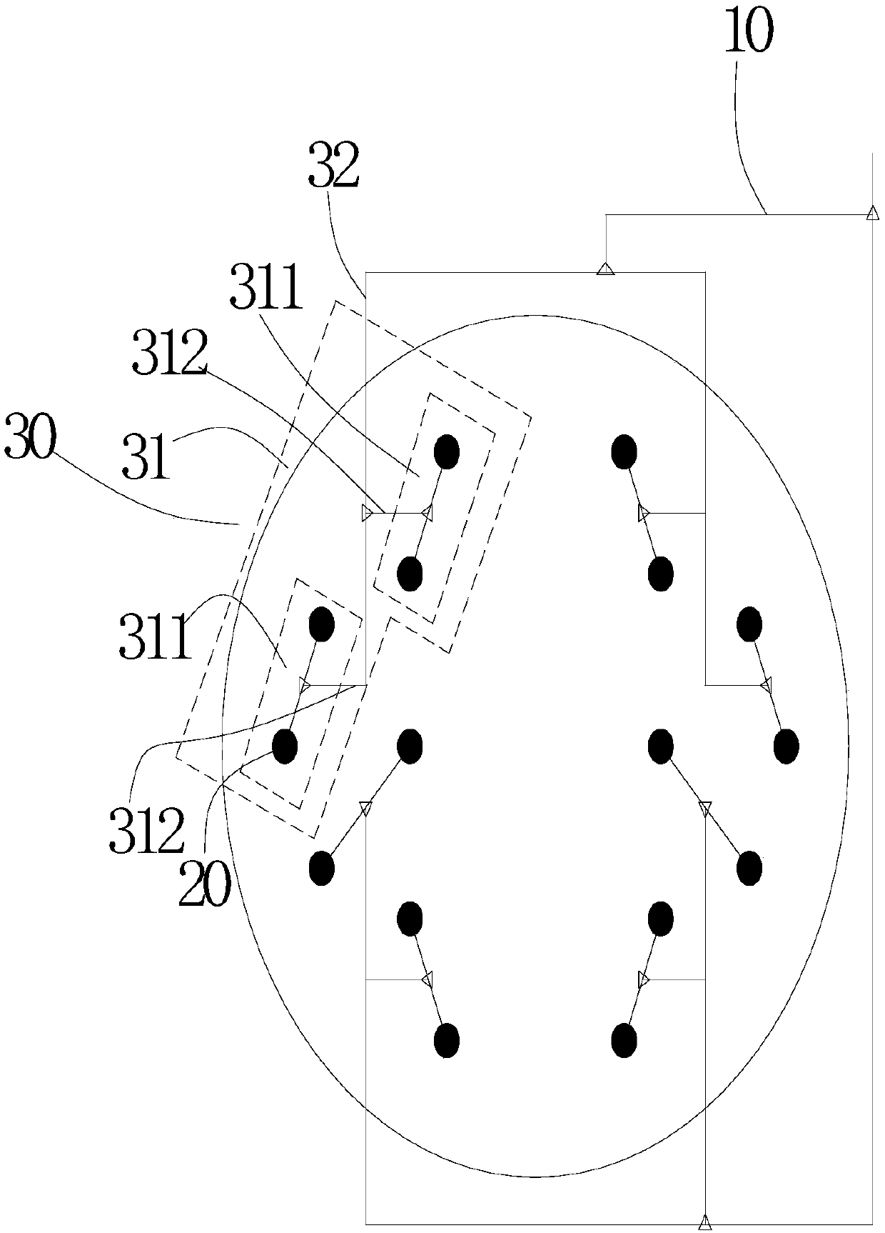
[0040] refer to figure 1 , an air circuit system for self-priming equipment, including an air source, an air supply main pipe 10 connected to the air source, several suction ports 20 respectively connected to the self-priming device, and a bronchial circuit assembly; the suction port When the number of 20 is M=4N, the bronchial circuit assembly includes N first bronchial circuits 30; wherein, N=4; the first bronchial circuit 30 includes two primary air circuit units 31 and primary connecting pipes 32, one The first-level air circuit unit 31 corresponds to the first-level connecting pipe 32; one end of each first-level connecting pipe 32 is connected to one end of the gas supply main pipe 10, and the other end of each first-level connecting pipe 32 is connected to a corresponding one. Stage gas circuit unit 31;

[0041] Each primary air circuit unit 31 includes two secondary air circuit units 311 and secondary connecting pipes 312, the secondary air circuit units 311 and the s...

Embodiment 2

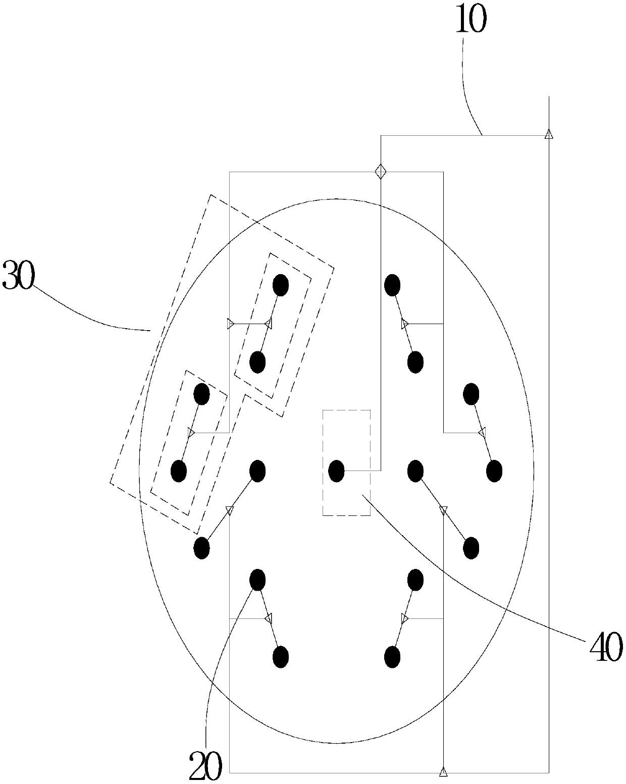
[0054] refer to figure 2 , the characteristics of this embodiment are: when the number of inspiratory ports M=4N+1, the bronchial pipeline assembly includes N first bronchial pipelines 30 and 1 second bronchial pipeline 40, wherein N=4; the second bronchial pipeline The road 40 includes an air suction port and a two-way pipe, and the air suction port of the second bronchial circuit is connected with the air supply main pipe through the two-way pipe.

[0055] As a preferred embodiment, the four first bronchial circuits are distributed in a ring, and the second bronchial circuit is placed in the middle.

[0056] Others are the same as in Example 1.

Embodiment 3

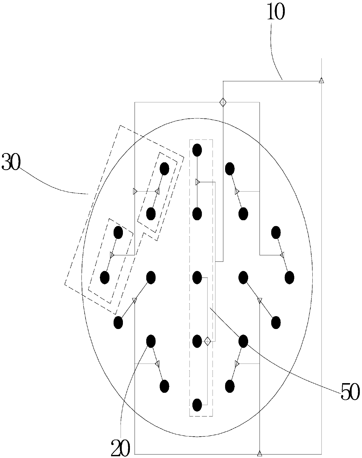
[0058] refer to image 3 , the characteristics of this embodiment are: when the number of inspiratory ports M=4N+1, the bronchial pipeline assembly includes 4 first bronchial pipelines 30 and 1 third bronchial pipeline 50, wherein N=5; the third bronchial pipeline The circuit includes five suction ports, a three-way pipe and a four-way pipe, two of the five suction ports are connected to one end of the air supply main pipe through the three-way pipe, and the other three of the five suction ports are The suction port is connected to one end of the gas supply main pipe through a four-way pipe.

[0059] As a preferred embodiment, the four first bronchial circuits are distributed in a ring, and the third bronchial circuit is placed in the middle.

[0060] Others are the same as in Example 1.


PUM


Abstract

The invention discloses an air channel system of a self-suction device and further discloses a manufacturing method of the air channel system of the self-suction device. The air channel system comprises an air source, an air supplying main pipe connected with the air source and a plurality of air suction openings and further comprises a branch air pipeline assembly which comprises at least two first branch air pipelines; each first branch air pipeline comprises two first-stage air channel unit and a first-stage connecting pipe, and the first-stage air channel units correspond to the first-stage connecting pipes in a one-to-one mode; each first-stage air channel unit comprises two second-stage air channel units and a second-stage connecting pipe, and the second-stage air channel units correspond to the second-stage connecting pipe in a one-to-one mode; and each second-stage air channel unit comprises the two corresponding air suction openings, and the two corresponding air suction openings of each second-stage air channel unit are connected to one end of the corresponding second-stage connecting pipe through three-way pipes. The air channel system and the manufacturing method have the characteristics that the air pumping pressure is sufficient, the air quantity is sufficient, and a pipe network is simple.

Description

technical field [0001] The invention relates to an air pipeline network, in particular to an air pipeline system of self-priming equipment and a manufacturing method thereof. Background technique [0002] At present, in the field of waste gas treatment of environmental protection technology, self-priming equipment such as jets, cavitators, and gas-liquid mixers are used more and more frequently, and more and more are used in the same area. It leads to the question of how to lay out the gas pipeline network. [0003] The layout of the gas pipeline network in the prior art is as follows: adjacent points (suction ports) are directly connected by pipelines and arranged along the pipelines to form straight pipelines or messy pipelines, and each straight pipeline connects several points (inhalation ports), the number of points is equal or not, and finally the straight pipes are connected to each other at the end to form a total gas path. The existing gas pipeline network has the...

Claims


Application Information

Patent Timeline
Patent Type & Authority Applications(China)
IPC IPC(8): F17D1/02
CPCF17D1/02
Inventor 黄国信韦东宁王克亮赵亚旗
Owner 佛山市柏益环保设备有限公司
Why Eureka
Try Eureka