Intelligent sampling and metering device for identifying magnetic-field interference and identification method
A technology of measuring device and sampling device, which is applied to measuring device, volume/mass flow generated by electromagnetic effect, and application of electromagnetic flowmeter to detect fluid flow, etc. interference, etc.
- Summary
- Abstract
- Description
- Claims
- Application Information
AI Technical Summary
Problems solved by technology
Method used
Image
Examples
Embodiment 1
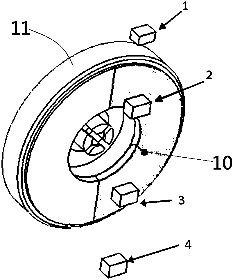
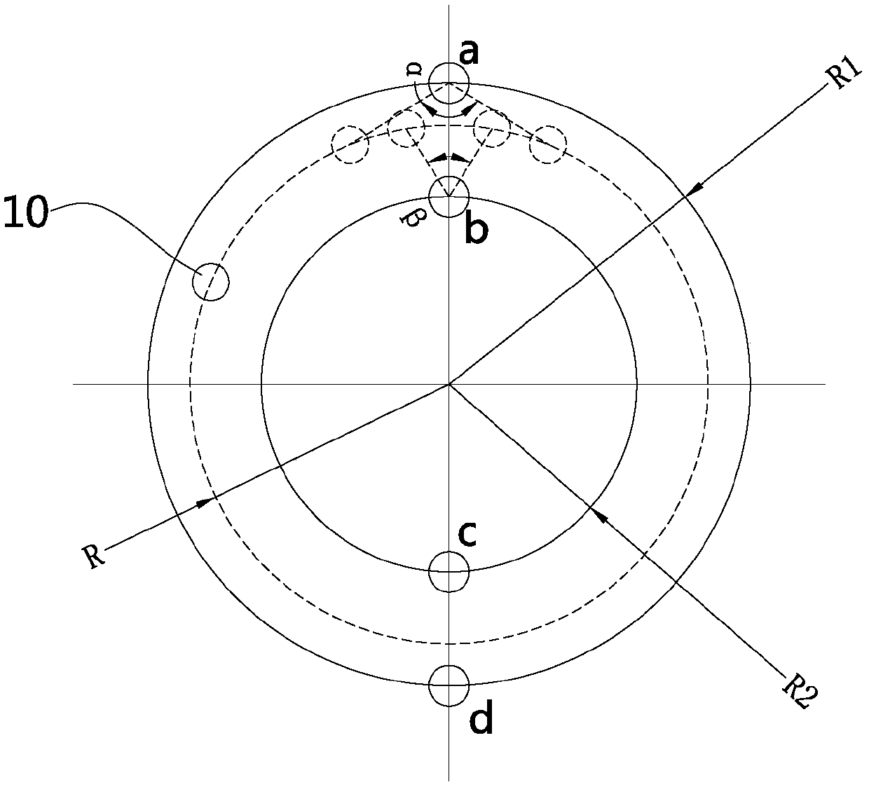
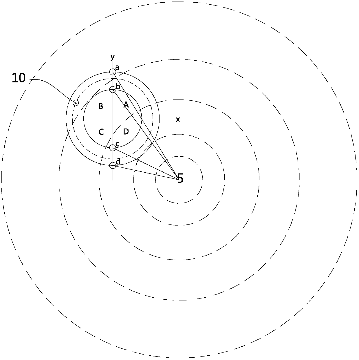
[0036] Such as Figures 1 to 2 As shown, the intelligent sampling and metering device in this embodiment can be a gas meter or a meter, including a metering device and a sampling device, and the metering device includes a metering code disc 11 and a magnet 10 installed on the metering code disc 11, and the magnet 10 is a magnet Or magnetic steel, preferred magnetic steel in the present embodiment, sampling device comprises control board (not shown in the figure) and the sensor group that is located on the control board, sensor group is installed on the opposite side of control board and measuring code disc 11, The sensor group in this preferred embodiment includes a first sensor group and a second sensor group distributed on two concentric circles, the first sensor group and the second sensor group respectively include several sensors distributed on the same circumference, and the magnetic steel The projection on the control board is located in the area between two concentric ...
Embodiment 2
[0057] Such as Figure 5 As shown, compared with Embodiment 1, the difference of this embodiment is that the line connecting sensor a and sensor d is a straight line passing through the center of the circle, the line connecting sensor b and sensor c is a straight line passing through the center of the circle, and the two straight lines The included angle between them is γ, satisfying 0°<γ<180°. Such a design can meet different installation layouts and performance requirements of devices, and it can also achieve the effect of this embodiment, which will not be described in detail here.
Embodiment 3
[0059] Such as Figure 6 As shown, compared with Embodiment 1, the difference of this embodiment is that the second sensor group in this embodiment includes sensor b and sensor c, and sensor b and sensor c are symmetrically distributed on both sides of sensor a or sensor d , that is, sensor b and sensor c take the y-axis connecting sensor a and sensor d as the symmetric axis, and are symmetrically distributed on both sides of the y-axis. Such a design can meet different installation layouts and performance requirements of devices, and it can also The effect of this embodiment is achieved, which will not be described in detail here.
PUM
 Abstract
Description
Claims
Application Information
 - R&D
- Intellectual Property
- Life Sciences
- Materials
- Tech Scout
- Unparalleled Data Quality
- Higher Quality Content
- 60% Fewer Hallucinations
Browse by: Latest US Patents, China's latest patents, Technical Efficacy Thesaurus, Application Domain, Technology Topic, Popular Technical Reports.
© 2025 PatSnap. All rights reserved.Legal|Privacy policy|Modern Slavery Act Transparency Statement|Sitemap|About US| Contact US: help@patsnap.com


