
Display device

一种显示装置、显示面板的技术,应用在仪器、计算、电数字数据处理等方向,能够解决限制加工工艺和材料的选择、可视角度小等问题,达到种类丰富、增加可视角度、降低加工难度的效果

Active Publication Date: 2018-02-27
SHANGHAI TIANMA MICRO ELECTRONICS CO LTD
View PDF6 Cites 9 Cited by
  • Summary
  • Abstract
  • Description
  • Claims
  • Application Information

AI Technical Summary

Problems solved by technology

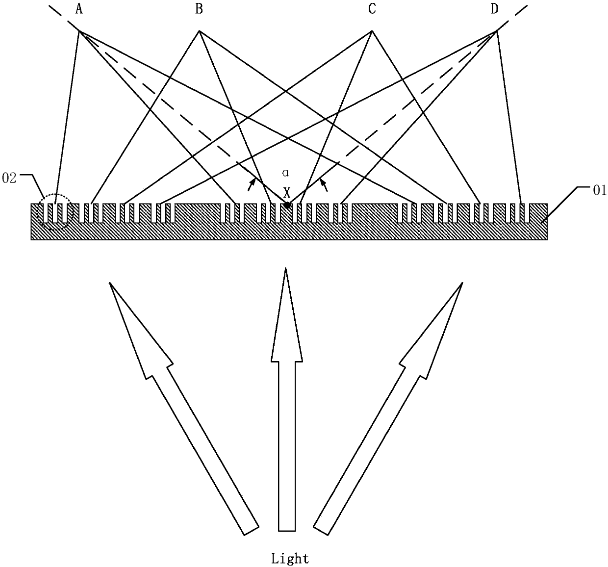
The viewing angle α of the 3D display device provided by the prior art is usually about 90°, and the viewing angle is relatively small.
[0007] In addition, the grating 02 must be processed on a transparent substrate 01 with a high refractive index. Usually, the transparent substrate 01 is made of glass material, which limits the selection of processing technology and materials.

Method used


Image

  • Display device
  • Display device
  • Display device

Examples


Embodiment Construction

[0029] Various exemplary embodiments of the present invention will now be described in detail with reference to the accompanying drawings. It should be noted that unless specifically stated otherwise, the relative arrangement, numerical expressions and numerical values ​​of the components and steps set forth in these embodiments do not limit the scope of the present invention.

[0030] The following description of at least one exemplary embodiment is actually only illustrative, and in no way serves as any limitation to the present invention and its application or use.

[0031] The technologies, methods, and equipment known to those of ordinary skill in the relevant fields may not be discussed in detail, but where appropriate, the technologies, methods, and equipment should be regarded as part of the specification.

[0032] In all the examples shown and discussed herein, any specific value should be interpreted as merely exemplary and not as limiting. Therefore, other examples of the...


PUM

PropertyMeasurementUnit
viewing angleaaaaaaaaaa
refractive indexaaaaaaaaaa

Abstract

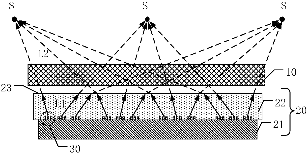
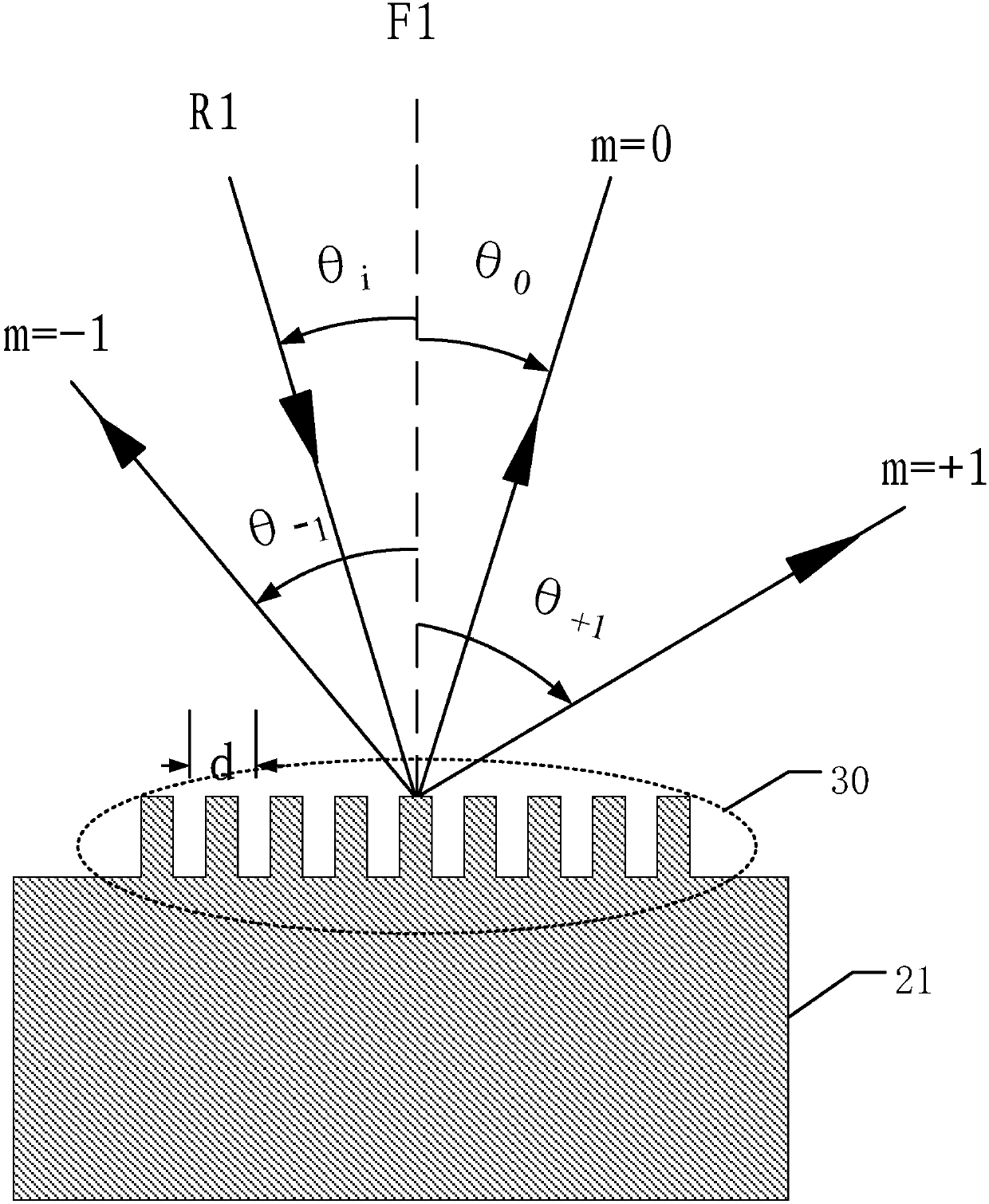
The invention discloses a display device, and belongs to the technical field of display. The display device comprises a display panel and a light modulation substrate which are arranged opposite to each other; the light modulation substrate comprises a substrate layer and a transparent dielectric layer, and the transparent dielectric layer is arranged on the side, close to the display panel, of the substrate layer; the substrate layer comprises a plurality of reflective grating structures and is covered with the transparent dielectric layer, and the surface of the side, away from the substratelayer, of the transparent dielectric layer is a transparent dielectric layer surface; the refractive index of the transparent dielectric layer is n, and n is greater than 1; light emitted from the display device converges into a plurality of luminous points at the exterior of the display device. Compared with the prior art, the visual angle of the display device is enlarged, and the processing difficulty is reduced.

Description

Technical field [0001] The present invention relates to the field of display technology, and more specifically, to a display device. Background technique [0002] With the development of display technology, 3D (Three-Dimensional) display technology has become one of the research and development directions of display technology. In a 3D display device, precise control of the propagation direction of light is required. [0003] In a 3D display device provided in the prior art, a transmissive grating is used to modulate the direction of light. By adjusting the period of the grating, the wavelength of the coherent light source, the incident direction of the coherent light source and other parameters, the direction of the emitted light can be modulated. [0004] Please refer to figure 1 , figure 1 It is a schematic diagram of a grating structure in a 3D display device provided in the prior art. Wherein, a plurality of transmissive gratings 02 are provided on the transparent substrate 0...

Claims


Application Information

Patent Timeline
Patent Type & Authority Applications(China)
IPC IPC(8): G02F1/1335G02B27/22G02B30/33
CPCG02F1/133504G02F1/133553G02B30/33G02F2201/305G02B5/1861G06F3/04815G02B5/3058G06F3/041G02F1/13363G06F3/0354G06F3/0362G02F1/133528G02B30/27
Inventor 杨帆牛磊马骏李嘉灵
Owner SHANGHAI TIANMA MICRO ELECTRONICS CO LTD
Learn More