
Electronic element high-efficiency vacuum gluing equipment

An electronic component, high-efficiency technology, applied in the manufacturing of electrical components, circuits, inductors/transformers/magnets, etc., can solve the problems of many processes, high manufacturing costs, complexity, etc., achieve good baking effect, save equipment costs, work Efficient effect

Pending Publication Date: 2018-02-27
DONGGUAN TB ELECTRONICS TECH CO LTD
View PDF0 Cites 19 Cited by
  • Summary
  • Abstract
  • Description
  • Claims
  • Application Information

AI Technical Summary

Problems solved by technology

[0003] The automatic gluing machine in the prior art is generally fixed by a fixture, and the inductance is rotated through the rotating fixture to apply glue. After the gluing is completed, the glue needs to be spread evenly. It can be seen that the gluing is performed by fixing the inductance through the clamp chuck. There are too many processes, too complicated, and the equipment manufacturing cost is high

Method used


Image

  • Electronic element high-efficiency vacuum gluing equipment
  • Electronic element high-efficiency vacuum gluing equipment
  • Electronic element high-efficiency vacuum gluing equipment

Examples


Embodiment Construction

[0045] The present invention will be further described below in conjunction with the accompanying drawings.

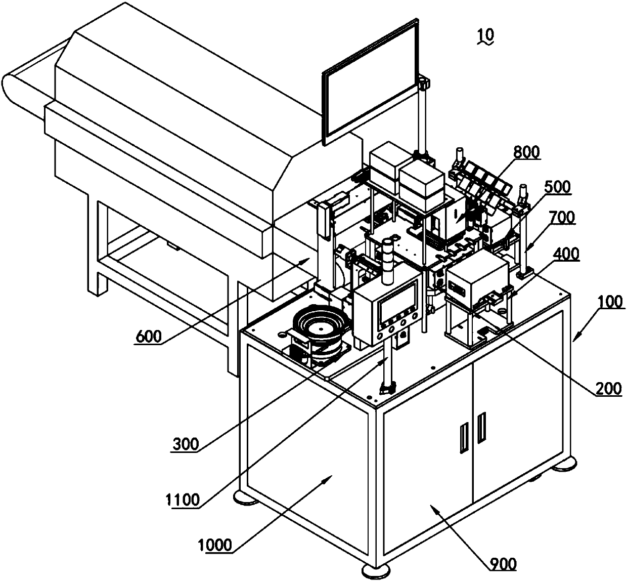
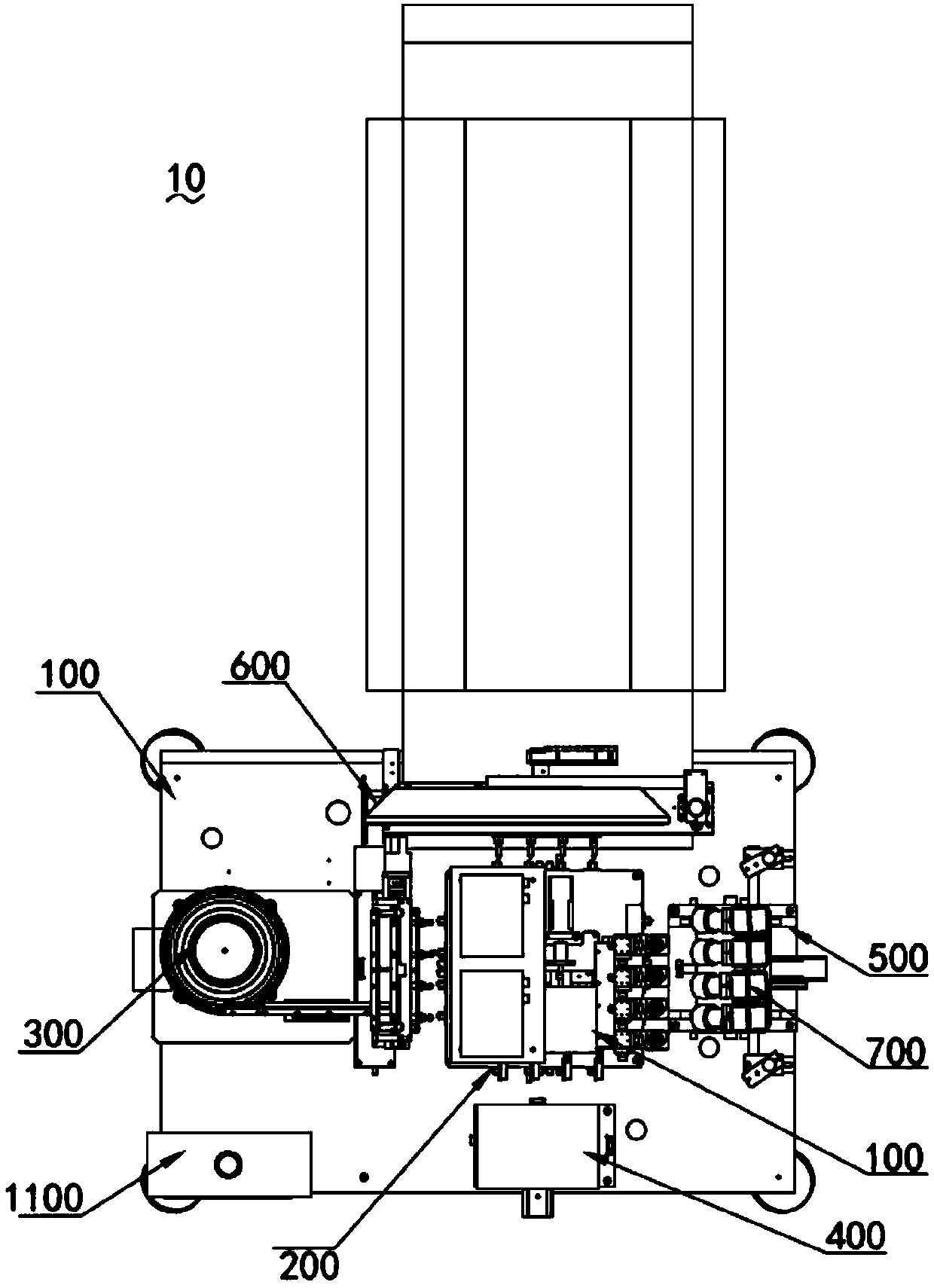
[0046] Such as Figure 1 ~ Figure 2 Shown, are respectively the three-dimensional top view of the present invention.

[0047] A high-efficiency vacuum gluing equipment 10 for electronic components, including a frame 100, a turntable mechanism 200 arranged on the frame 100, a feeding mechanism 300, a positioning mechanism 400, and a rotating mechanism arranged on the frame 100 around the turntable mechanism 200 500 and the unloading mechanism 600, the detection mechanism 700 fixed to the frame 100 above the rotating mechanism 500, the gluing mechanism 800 installed on the frame 100 above the turntable mechanism 200; the vacuum mechanism 900 and electric The control mechanism 1000 is connected with the electric control mechanism 1000 and is fixed on the control mechanism 1100 of the frame 100. The vacuum mechanism 900 is connected with the feeding mechanism 300, the bla...


PUM


Abstract

The invention relates to the technical field of electronic element gluing, and particularly relates to electronic element high-efficiency vacuum gluing equipment, which comprises a rack, a turntable mechanism, a loading mechanism, a positioning mechanism, a rotating mechanism, an unloading mechanism, a detecting mechanism, a gluing mechanism, a vacuum mechanism, an electric control mechanism and acontrol mechanism, wherein the turntable mechanism is arranged on the rack; the loading mechanism, the positioning mechanism, the rotating mechanism and the unloading mechanism are arranged on the rack and around the turntable mechanism; the detecting mechanism is fixed on the rack and above the rotating mechanism; the gluing mechanism is mounted on the rack and above the turntable mechanism; thevacuum mechanism and the electric control mechanism are arranged in the rack; the control mechanism is connected with the electric control mechanism and is fixed on the rack; the vacuum mechanism isconnected with the loading mechanism, the unloading mechanism and the turntable mechanism; the electric control mechanism is electrically connected with the turntable mechanism, the loading mechanism,the positioning mechanism, the rotating mechanism, the unloading mechanism, the vacuum mechanism and the control mechanism. The equipment provided by the invention has the advantages of full-automatic overall operation, high gluing quality of electronic elements, high gluing efficiency and high automation degree.

Description

technical field [0001] The invention relates to the technical field of electronic component gluing, in particular to a high-efficiency vacuum gluing equipment for electronic components. Background technique [0002] As the application of electronic products becomes more and more extensive, the production of various components in electronic products is becoming more and more important, and inductors, as one of the three major components, are becoming more and more important. Usually, the production of power inductors requires a copper wire winding process. After the copper wire is wound, glue needs to be applied to the position of the copper wire. This process is usually completed by an automatic glue applicator or manual glue application. [0003] The automatic gluing machine in the prior art is generally fixed by a fixture, and the inductance is rotated through the rotating fixture to apply the glue. After the gluing is completed, the glue needs to be spread evenly. It can ...

Claims


Application Information

Patent Timeline
Patent Type & Authority Applications(China)
IPC IPC(8): H01F41/00
CPCH01F41/005
Inventor 翁春雨温小金黄天碧黄文祥张健
Owner DONGGUAN TB ELECTRONICS TECH CO LTD
Learn More