Main oil duct sand core of diesel engine frame and manufacturing method thereof

A technology of oil channel sand core and main oil channel, applied in manufacturing tools, cores, casting and forming equipment, etc. question

Inactive Publication Date: 2018-03-02
四川共享铸造有限公司
View PDF8 Cites 3 Cited by
  • Summary
  • Abstract
  • Description
  • Claims
  • Application Information

AI Technical Summary

Problems solved by technology

[0002] Now in order to get enough power, the engine is getting bigger and bigger, and as the size of the engine becomes bigger, some parts are also getting bigger, and the main oil passage of the engine is also getting larger. Now the length of the main oil passage of many large engines It is several meters long and has a diameter of more than 100mm. In the casting process, in order to obtain a larger main oil passage, the sand core of the main oil passage is also becoming longer and larger, but because the sand core of the main oil passage is too long and too large, Self-gravity will cause deformation of the sand core in the main oil channel, and it is easy to cause problems such as large assembly accuracy errors during the assembly of the hoisting sand core, which will lead to the scrapping of castings
[0003] At present, the main oil passages of domestic diesel engine frames (in-line and L-type) are cored manually or by equipment, and the lower cores of the main oil passages are supported or fixed by core supports. There is no fusion between the core supports and the frame body. Leakage defects occurred during the pressure test, causing the frame to be scrapped, and there is currently no good way to solve it

Method used


Image

  • Main oil duct sand core of diesel engine frame and manufacturing method thereof
  • Main oil duct sand core of diesel engine frame and manufacturing method thereof
  • Main oil duct sand core of diesel engine frame and manufacturing method thereof

Examples


Embodiment Construction

[0023] In order to enable those skilled in the art to better understand the technical solutions of the present invention, the present invention will be further described in detail below in conjunction with specific embodiments.

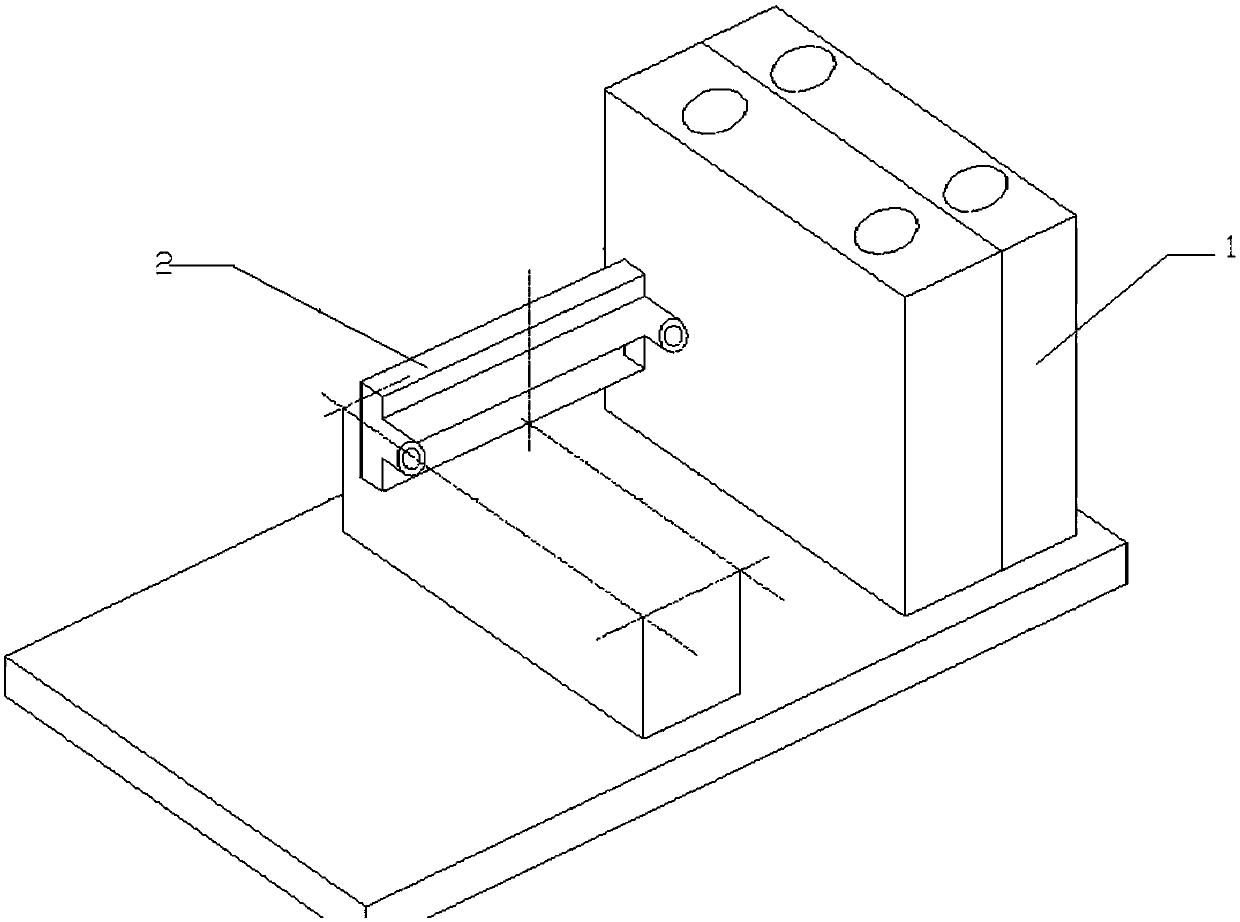
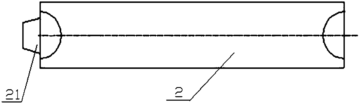
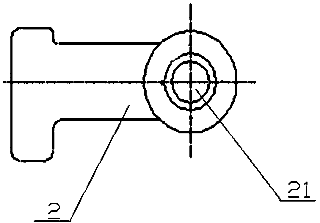
[0024] Such as Figure 1-Figure 7 As shown, the main core body 1 of the present invention and the main oil passage sand core arranged on the main core body, the main oil passage sand core is divided into several according to the number of frame cylinders and the center size of each gear crankshaft as the parting surface. Segmented oil channel sand core 2; the segmented oil channel sand core 2 is composed of a core bone 3 and a sand body wrapped on the core bone 3; one end of the segmented oil channel sand core 2 is provided with a positioning core head 21, and the other end is A positioning core groove 22 is provided; the positioning core head 21 of the oil channel sand core 2 of the previous segment is embedded in the positioning core groove 22 of th...


PUM


Abstract

The invention discloses a main oil duct sand core of a diesel engine frame and a manufacturing method thereof. The main oil duct sand core comprises a main core body and a main oil duct sand core bodyarranged on the main core body; the main oil duct sand core body is divided into a plurality of oil duct sand core subsections with the center of each gear of crank as the parting surface according to the number of cylinder bodies of the diesel engine frame; each oil duct sand core subsection is composed of a core rod and a sand body wrapping the core rod; positioning core heads are arranged at one ends of the oil duct sand core subsections, and positioning core grooves are formed in the other ends of the oil duct sand core subsections; the positioning core heads of the front oil duct sand core subsections are inlaid in the positioning core grooves of the rear oil duct sand core subsections for connection; and the main oil duct sand core further comprises two side core heads arranged at the front and rear ends of the multiple connected oil duct sand core subsections. Through the sectioning casting technology of the main oil duct sand core, the perpendicularity and concentricity of a main oil duct are guaranteed, and the casting defect of leaking in pressure testing is overcome thoroughly.

Description

technical field [0001] The invention relates to a sand core used for casting the main oil channel of an in-line or L-shaped frame and a manufacturing method of the sand core. Background technique [0002] Now in order to get enough power, the engine is getting bigger and bigger, and as the size of the engine becomes bigger, some parts are also getting bigger, and the main oil passage of the engine is also getting larger. Now the length of the main oil passage of many large engines It is several meters long and has a diameter of more than 100mm. In the casting process, in order to obtain a larger main oil passage, the sand core of the main oil passage is also becoming longer and larger, but because the sand core of the main oil passage is too long and too large, Self-gravity will cause deformation of the sand core in the main oil channel, and the assembly of the hoisting sand core will easily cause problems such as large assembly accuracy errors, which will lead to scrapping ...

Claims


Application Information

Patent Timeline
Patent Type & Authority Applications(China)
IPC IPC(8): B22C9/10B22C9/24
CPCB22C9/103B22C9/24
Inventor 刘建平
Owner 四川共享铸造有限公司
Why Eureka
Try Eureka