Rapid positioning device for traveling block lifting beam

A technology of positioning device and hoisting beam, which is applied in the direction of load block, transportation and packaging, load hoisting element, etc. Reduce labor intensity and installation risk, the effect of simple structure

Active Publication Date: 2018-03-02
BAOJI PETROLEUM MASCH CO LTD +2
View PDF5 Cites 4 Cited by
  • Summary
  • Abstract
  • Description
  • Claims
  • Application Information

AI Technical Summary

Problems solved by technology

[0004] The object of the present invention is to provide a quick positioning device for traveling car crane beams, which solves the problems of high assembly strength of traveling car crane beams, difficult maintenance and low work efficiency existing in the prior art

Method used


Image

  • Rapid positioning device for traveling block lifting beam
  • Rapid positioning device for traveling block lifting beam
  • Rapid positioning device for traveling block lifting beam

Examples


Embodiment Construction

[0019] The present invention will be described in detail below in conjunction with the accompanying drawings and specific embodiments.

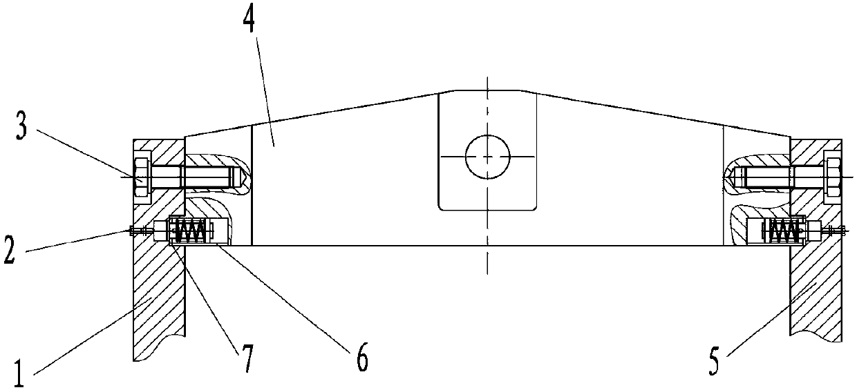
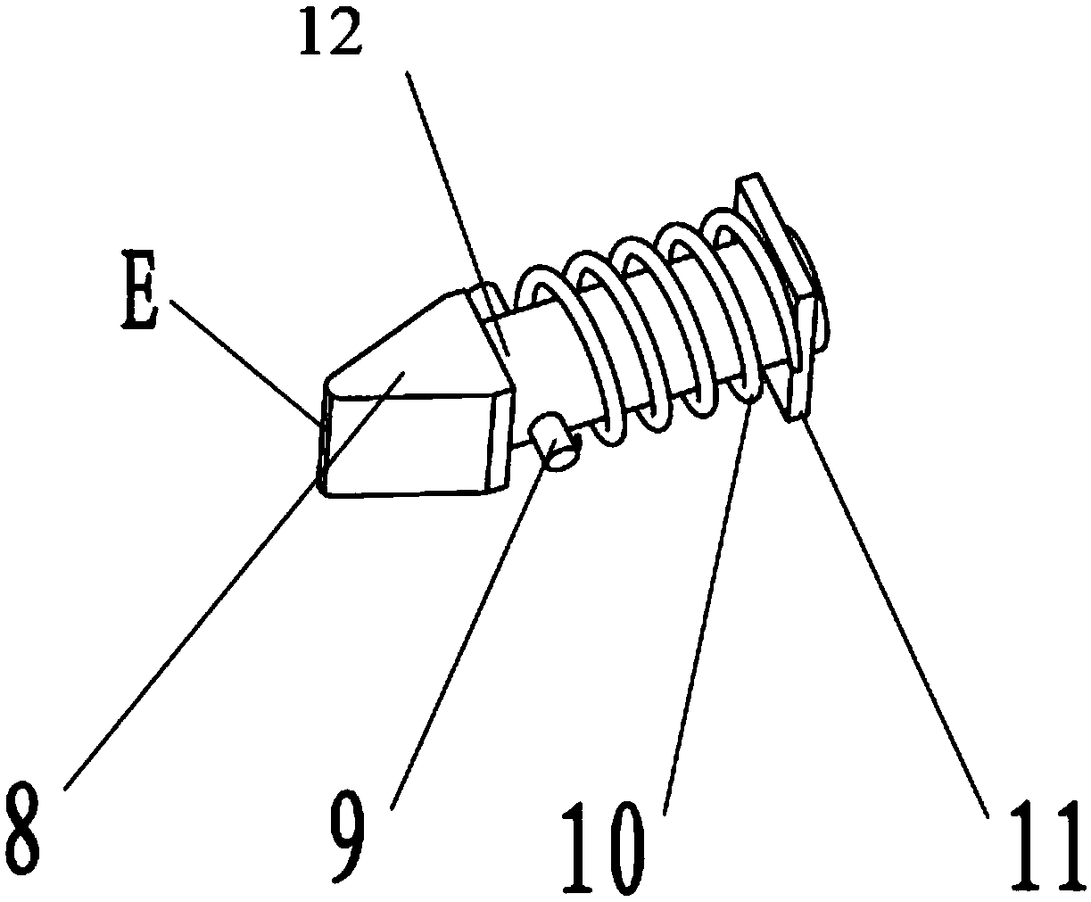
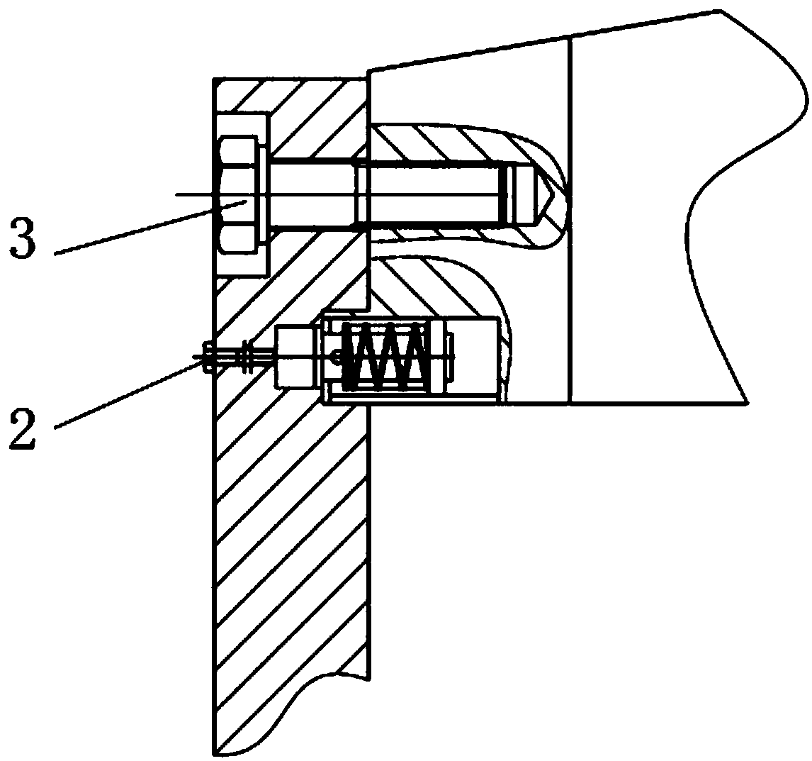
[0020] The present invention is a quick positioning device for traveling vehicle suspension beam, such as figure 1 , including a left panel 1, a deadbolt assembly 12, a suspension beam 4, and a right panel 5. Such as figure 2 As shown, the assembly of the deadbolt assembly 12 is first completed, the limit pin shaft 9 is fixed in the through hole of the V-shaped deadbolt 8, the spring 10 is set on the V-shaped deadbolt 8, and the tail of the V-shaped deadbolt 8 is set on the guide support plate 11. The entire deadbolt assembly 12 is installed at A of the hanging beam 4 (the center position of the end), the lower part is supported and fixed by the bottom baffle 6, the front part is clamped and fixed by the limit plate 7, and the hanging beam 4 is embedded in the left side plate 1 and right side plate 5, fasten with bolt 3.

[0021] refer t...


PUM


Abstract

The invention discloses a rapid positioning device for a traveling block lifting beam. The rapid positioning device comprises a left side plate, the lifting beam, a right side plate and lock tongue assemblies. The lock tongue assemblies are mounted in the central positions of the ends of the lifting beam, and the lower portions of the lock tongue assemblies are fixed with bottom baffles in a supported mode, and the front portions of the lock tongue assemblies are fixed with limiting plates in a clamped mode. The lifting beam is inlaid in the left side plate and the right side plate and then fastened through bolts. By controlling the lock tongue assemblies to extend or retract in the predetermined positions, rapid positioning and assembling of the traveling block lifting beam are achieved,the labor intensity and risks of workers are reduced greatly, and the assembling time is saved. The rapid positioning device is convenient and reliable to use and easy and convenient to operate and maintain.

Description

technical field [0001] The invention belongs to the technical field of oil and gas equipment manufacturing, and relates to a quick positioning device for a crane beam. Background technique [0002] The traveling block is one of the important supporting equipment for oil drilling rigs and workover rigs. The main function of the traveling block suspension beam is to connect the traveling block and its suspension when the drilling wire rope breaks down and needs to be repaired or replaced. The lower equipment is suspended under the crown block, and then the drilling wire rope is maintained and replaced. [0003] At present, there are two main forms of traveling car suspension beam structure: integral casting structure and integral forging structure. The overall casting structure has a long manufacturing cycle, many casting defects, and a low survival rate. For large traveling vehicles, the axial span is large. Difficult to guarantee. The suspension beam with integral forged ...

Claims


Application Information

Patent Timeline
Patent Type & Authority Applications(China)
IPC IPC(8): B66C11/24
CPCB66C11/24
Inventor 惠川川叶强祝贺高勇超田凤仙
Owner BAOJI PETROLEUM MASCH CO LTD
Why Eureka
Try Eureka