Eureka AIR delivers breakthrough ideas for toughest innovation challenges, trusted by R&D personnel around the world.

Exhaust valve structure for exhaust system and control method of exhaust valve structure

A technology of exhaust system and control method, applied in the direction of engine control, output power, machine/engine, etc., can solve the problem that the opening and closing cannot fully meet the target requirements of acoustic opening and closing, the back pressure index requirements are getting lower and lower, Difficult to meet the acoustical requirements and other issues, to achieve the effect of simple structure, reduce "roaring" noise, and optimize design

Active Publication Date: 2018-03-02
JAPHL POWERTRAIN SYST
View PDF8 Cites 0 Cited by
  • Summary
  • Abstract
  • Description
  • Claims
  • Application Information

AI Technical Summary

Problems solved by technology

[0002] With the reduction of vehicle weight and fuel consumption index, and the increase of engine power, the noise of the engine exhaust system will also increase. The requirements for the back pressure index of the air system are getting lower and lower. Therefore, the requirements for the NVH performance of the exhaust system are constantly increasing, making it difficult to meet the acoustic requirements of all acoustic conditions with the traditional purely resistive muffler acoustic design, especially at idle speed or at low and medium speeds. The low-frequency "roaring" noise of the speed is particularly obvious. For some special working conditions such as deceleration, the noise problem caused by the calibration characteristics of the engine cannot be eliminated by the design of the transmission exhaust system.
Based on these problems, it is possible to add an active control valve and a passive control valve to the exhaust system. However, the working principle of the passive control valve is to open and close the valve by lowering the air pressure. The opening and closing cannot fully comply with the acoustic opening and closing. Goal requirements, there are limitations

Method used


Image

  • Exhaust valve structure for exhaust system and control method of exhaust valve structure
  • Exhaust valve structure for exhaust system and control method of exhaust valve structure
  • Exhaust valve structure for exhaust system and control method of exhaust valve structure

Examples


Embodiment Construction

[0023] Below with reference to the accompanying drawings, through the description of the embodiments, the specific embodiments of the present invention, such as the shape, structure, mutual position and connection relationship between the various parts, the role and working principle of the various parts, etc., will be further described. Detailed instructions:

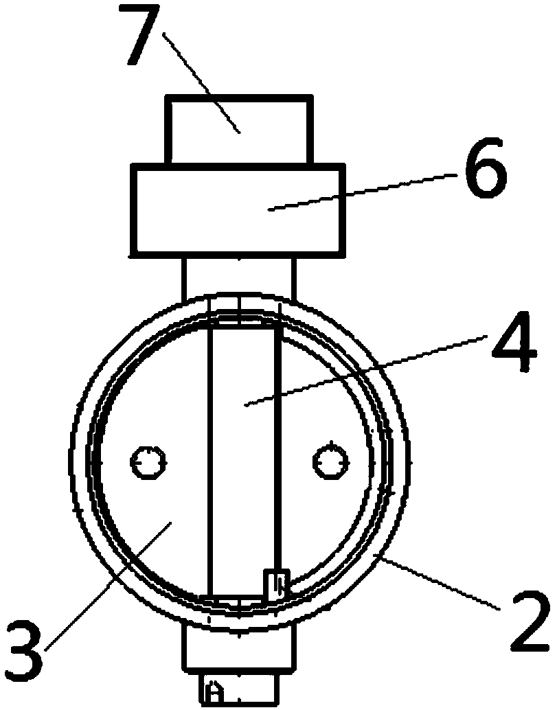
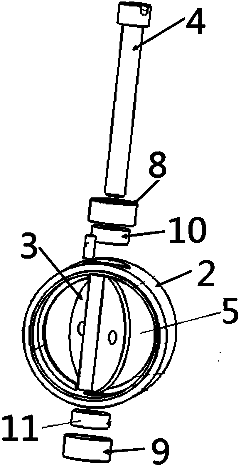
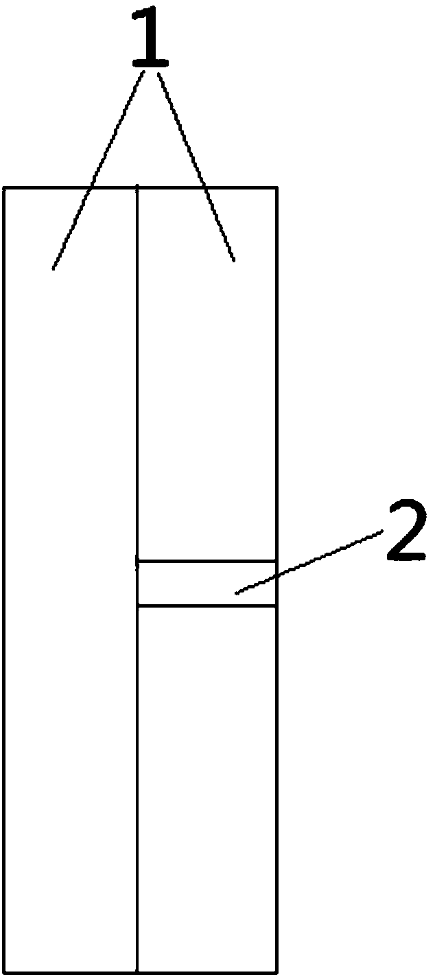
[0024] as attached figure 1 - attached Figure 4 As shown, the present invention is an exhaust valve structure of an exhaust system, the exhaust system includes a plurality of tailpipes 1, and the exhaust valve structure of the exhaust system includes a valve seat 2, a valve plate 3, a valve seat 2 Installed in one tail pipe 1 among the plurality of tail pipes 1, the valve 3 is installed in the valve seat cavity 5 of the valve seat 2 through the rotating shaft 4, the rotating shaft 4 is connected with the motor 6, and the motor 6 is connected with the control part 7 to control Component 7 is connected with the engine...


PUM


Abstract

The invention provides an exhaust valve structure for an exhaust system and further relates to a control method of the exhaust valve structure for the exhaust system. The exhaust valve structure for the exhaust system is applied to the technical field of engine exhaust system parts. According to the exhaust valve structure for the exhaust system, a motor (6) is connected with a control part (7), and the control part (7) is connected with an engine rotating speed signal sensor in a vehicle CAN signal; the interior of the control part (7) is arranged to be of a structure storing valve piece close rotating speed range data; when an engine works, the rotating speed of the engine is within the valve piece close rotating speed data range; and the control part (7) is arranged to be of a structurewhich can control the motor (6) to rotate to drive a valve piece (3) to close a valve seat cavity (5) of a valve seat (2). According to the exhaust valve structure for the exhaust system and the control method of the exhaust valve structure, the 'roaring' noise generated when the engine works can be effectively reduced, the low back pressure of the medium-high rotating speed is kept, and the performance of the exhaust system is improved.

Description

technical field [0001] The invention belongs to the technical field of engine exhaust system components, and more specifically relates to an exhaust system exhaust valve structure, and the invention also relates to a control method for the exhaust system exhaust valve structure. Background technique [0002] With the reduction of vehicle weight and fuel consumption index, and the increase of engine power, the noise of the engine exhaust system will also increase. The requirements for the back pressure index of the air system are getting lower and lower. Therefore, the requirements for the NVH performance of the exhaust system are constantly increasing, making it difficult to meet the acoustic requirements of all acoustic conditions with the traditional purely resistive muffler acoustic design, especially at idle speed or at low and medium speeds. The low-frequency "roaring" noise of the speed is particularly obvious. For some special working conditions such as deceleration, ...

Claims


Application Information

Patent Timeline
Patent Type & Authority Applications(China)
IPC IPC(8): F02D13/02
CPCF02D13/0242F02D2200/101
Inventor 严清梅姜倩范礼于芳刘玉洁戴国民周明方平周运花曹树根
Owner JAPHL POWERTRAIN SYST
Why Eureka
Eureka Blog
Learn More