
Embracing hoop device based on triangular structure

A triangular structure and hoop plate technology, applied in the direction of pipeline supports, pipes/pipe joints/pipes, mechanical equipment, etc., can solve the problems affecting the connection and sealing effect of new pipe sections, unable to ensure the stability of oil pipelines, unable to guarantee the leveling and other problems , to avoid friction damage, enhance stability and good wear resistance

Inactive Publication Date: 2018-03-02
弘毅天承知识产权股份有限公司
View PDF1 Cites 9 Cited by
  • Summary
  • Abstract
  • Description
  • Claims
  • Application Information

AI Technical Summary

Problems solved by technology

The problem with this method is that when the diameter of the pipe is large, two people must operate at the same time to complete the work of drawing the line, which is a waste of manpower, and cutting according to the drawn line is often impossible to ensure that it is even, affecting the final connection with the new pipe section The connection and sealing effect
The hoop in this technical solution will keep the position of the cutting ring fixed, ensuring that the cutter cuts the oil pipeline smoothly. However, this technical solution still has the following disadvantages: 1. The two ends of the semicircular shell A are respectively slidably arranged on the The size of the hoop can only be fine-tuned in the two ends of the semicircular shell B, which can be adapted to oil pipelines of different sizes to a certain extent, so that the application of the hoop has great limitations; 2. Although the front end of the slot is The arc-shaped structure enables the hoop to be more firmly set on the oil pipeline, but the arc-shaped mechanism is fixed, which cannot guarantee the stability of the oil pipeline clamping

Method used


Image

  • Embracing hoop device based on triangular structure
  • Embracing hoop device based on triangular structure
  • Embracing hoop device based on triangular structure

Examples


Embodiment Construction

[0026] In order for those skilled in the art to better understand the present invention, the present invention will be further described in detail below in conjunction with the accompanying drawings and the following embodiments.

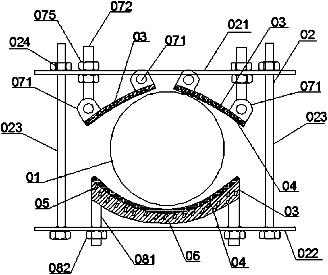
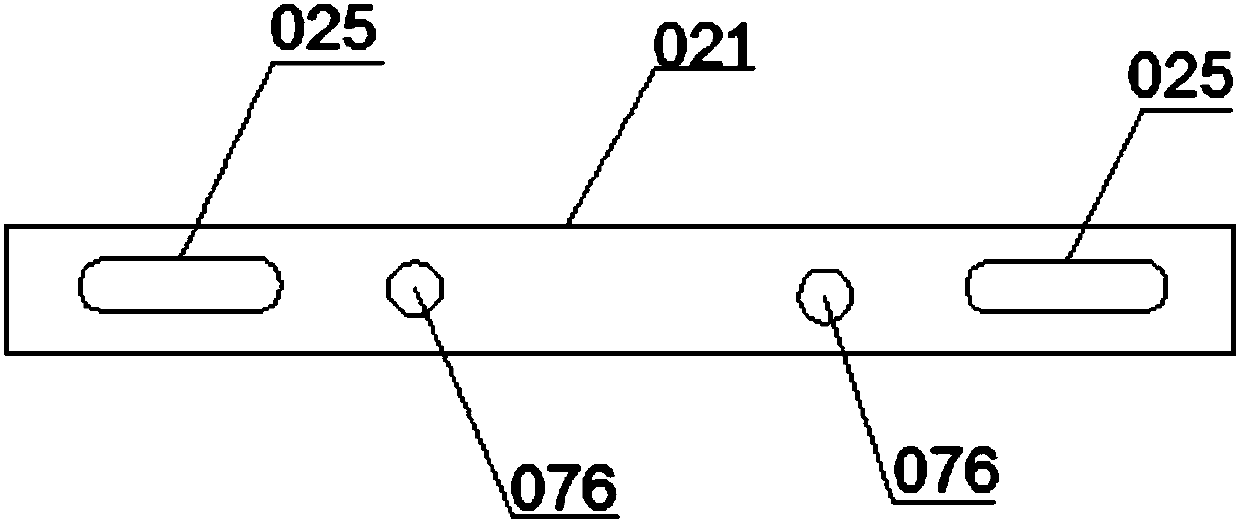
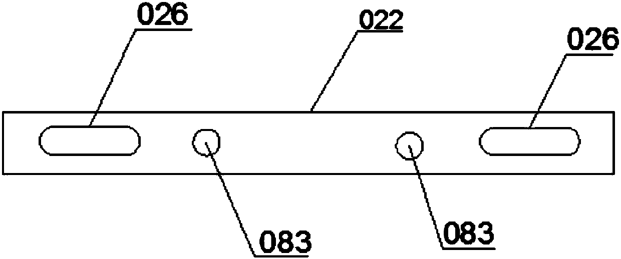
[0027] Please refer to Figure 1 to Figure 4 As shown, this embodiment provides a hoop device based on a triangular structure, including a support mechanism 02 for hugging the periphery of the oil pipeline 01, and an adjustment assembly for adjusting the distance between the support mechanisms 02 and locking them Specifically, the support mechanism 02 includes an upper support plate 021 and a lower support plate 022, and the adjustment assembly includes two locking screws 023 and lock nuts 024 vertically connected between the upper support plate 021 and the lower support plate 022, and the upper The support plate 021 and the lower support plate 022 are respectively provided with a first strip-shaped hole 025 and a second strip-shaped hole 026 . Uti...


PUM

PropertyMeasurementUnit
Thicknessaaaaaaaaaa

Abstract

The invention discloses a hoop device based on a triangular structure, relates to the technical field of oil pipeline hoops, and avoids the inability to ensure the stability of the oil pipeline clamping in the prior art; it includes a support mechanism for hugging the oil pipeline periphery and an adjustment assembly for adjusting the distance between the support mechanisms and locking them. The support mechanism includes an upper support plate and a lower support plate oppositely arranged. There are three hoop plates and three sets of hoop plates for contacting the oil pipeline inside the support mechanism. An adjustable component that supports the hoop plate and is vertically connected with the support plate. The materials of the three hoop plates are all made of NBR. The three sets of adjustable components can make the corresponding hoop plate radially adjusted along the oil pipeline. A hollow cavity filled with a low-melting-point metal alloy is arranged in the hoop plate, and a heater for heating the low-melting-point metal alloy is arranged in the hollow cavity. By implementing the technical solution, the ductile triangular hoop mechanism is used to realize the stability of clamping the oil pipeline.

Description

technical field [0001] The invention relates to the technical field of oil pipeline hoops, in particular to a hoop device based on a triangular structure. Background technique [0002] The transportation of oil needs to rely on oil pipelines of different diameters. In the oil industry, long pipelines need to be laid for oil transportation. However, because most of the oil pipelines are laid in relatively harsh environments, leakage and rupture often occur. If the damage is too large to repair welding, it is necessary to cut off the damaged part and replace it with a new pipe in time. During the replacement process, it is necessary to ensure that the cut pipe is flat. But existing operation is generally surrounded the outer wall of oil pipeline by a people with circle band, and another people draws a line along circle band with special stone pen, then cuts along the line drawn. The problem with this method is that when the diameter of the pipe is large, two people must opera...

Claims


Application Information

Patent Timeline
IPC IPC(8): F16L3/10F16L3/20
CPCF16L3/1066F16L3/20
Inventor 赵红昌陈伊苒
Owner 弘毅天承知识产权股份有限公司
Learn More