Voltage automatic regulation circuit for electric vehicle
An electric vehicle, automatic adjustment technology, applied in the direction of adjusting electrical variables, control/regulating systems, electrical components, etc., can solve problems such as changes, and achieve the effect of ensuring changes
- Summary
- Abstract
- Description
- Claims
- Application Information
AI Technical Summary
Problems solved by technology
Method used
Image
Examples
Embodiment 1
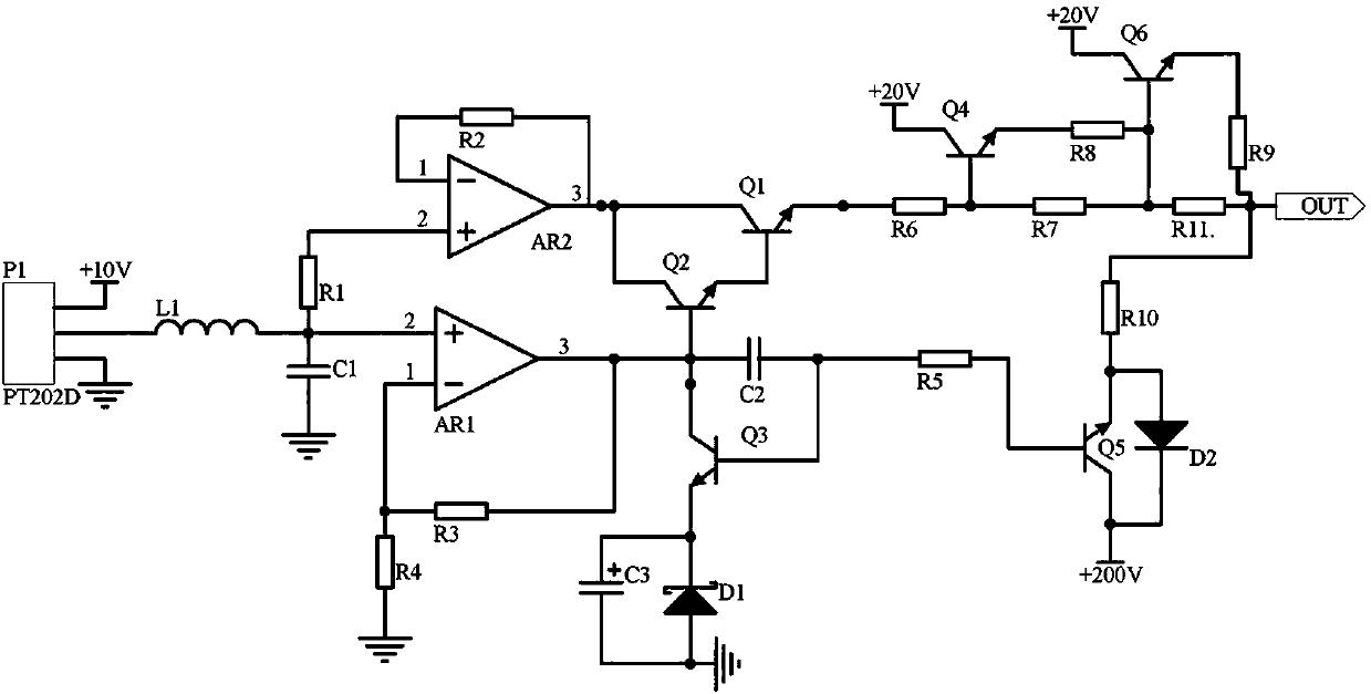
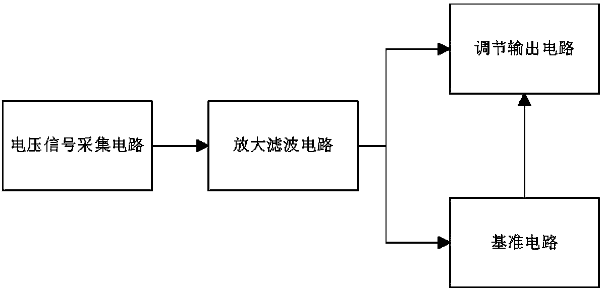
[0013] Embodiment 1, the electric vehicle voltage automatic adjustment circuit includes a voltage signal acquisition circuit, an amplification and filtering circuit, a reference circuit and an adjustment output circuit. The operational amplifiers AR1 and AR2 amplify the input signal of the voltage signal acquisition circuit, and use the triode Q1, Q2, capacitor C2 and triode Q3 to form a compound circuit for filtering. The signal output by the amplifying and filtering circuit is divided into two circuits, and one control reference circuit is the electric vehicle. The output port of the power supply provides the base voltage, and the other control and adjustment output circuit uses the principle of resistance voltage division to adjust the voltage to control the output voltage of the output port of the power supply;
[0014] Said amplification filter circuit utilizes operational amplifiers AR1 and AR2 to proportionally amplify the signal input by the voltage signal acquisition c...
Embodiment 2
[0015] Embodiment 2, on the basis of Embodiment 1, the voltage signal acquisition circuit selects the voltage transformer P1 model as PT202D to collect the output voltage of the power supply when the electric vehicle is running, and the power supply terminal of the voltage transformer P1 is connected to the power supply +10V. The ground terminal of the voltage transformer P1 is grounded, the output terminal of the voltage transformer P1 is connected to one end of the inductor L1, the other end of the inductor L1 is connected to one end of the capacitor C1, and the other end of the capacitor C1 is grounded.
Embodiment 3
[0016] Embodiment 3, on the basis of Embodiment 1, the reference circuit uses the triode Q5 to receive the signal output by the amplifying and filtering circuit. When the electric vehicle starts normally, the signal output by the amplifying and filtering circuit can turn on the triode Q5. At this time, the power supply +200V flows into the output port of the power supply after being divided by the transistor Q5 and the resistor R10, which is to supply power for electric vehicles. The voltage received by the output port of the power supply is +200V from the power supply plus +100V from the input voltage signal of the amplifying and filtering circuit, which is actually an electric vehicle. The power supply takes +200V as an example. When the electric vehicle changes speed during driving, the voltage signal collected by the voltage signal acquisition circuit becomes abnormally large, and the triode Q2 and Q1 are turned on. At this time, there are three levels of voltage regulation....
PUM
 Abstract
Description
Claims
Application Information
 - R&D
- Intellectual Property
- Life Sciences
- Materials
- Tech Scout
- Unparalleled Data Quality
- Higher Quality Content
- 60% Fewer Hallucinations
Browse by: Latest US Patents, China's latest patents, Technical Efficacy Thesaurus, Application Domain, Technology Topic, Popular Technical Reports.
© 2025 PatSnap. All rights reserved.Legal|Privacy policy|Modern Slavery Act Transparency Statement|Sitemap|About US| Contact US: help@patsnap.com


