
Respiratory phase detection locator

A technology of respiratory phase and locator, which is applied in the evaluation of respiratory organs and other directions, can solve problems such as complications, achieve the effects of easy observation and operation, improve monitoring accuracy, and reduce the risk of complications

Pending Publication Date: 2018-03-06
上海墨汇机器人科技有限公司
View PDF2 Cites 0 Cited by
  • Summary
  • Abstract
  • Description
  • Claims
  • Application Information

AI Technical Summary

Problems solved by technology

[0002] In clinical treatment, when performing puncture aspiration biopsy on the human chest and abdomen and treating tumors with microwave, radio frequency or freezing, the puncture needle must be inserted to the lesion (tumor) before suction or microwave, radio frequency and other treatments are performed. The location of the lesion (tumor) needs to be determined by CT. After the CT scan, the doctor reads the CT film and determines the puncture site according to the determined direction and angle. Since the patient is breathing continuously, even if the patient is asked to hold his breath, every breath will It is impossible to be at the same time phase, so the patient’s respiratory phase during the CT scan and the patient’s respiratory phase during the doctor’s puncture may be different, so that the doctor cannot puncture to the appropriate site, because the doctor cannot see the lesion (tumor) when inserting the needle ), and the location of the lesion moves with the patient's breathing, especially for deep masses, a small angle difference will cause a large deviation. Although repeated corrections and repeated punctures, there is still a risk of complications

Method used


Image

  • Respiratory phase detection locator
  • Respiratory phase detection locator

Examples


Embodiment

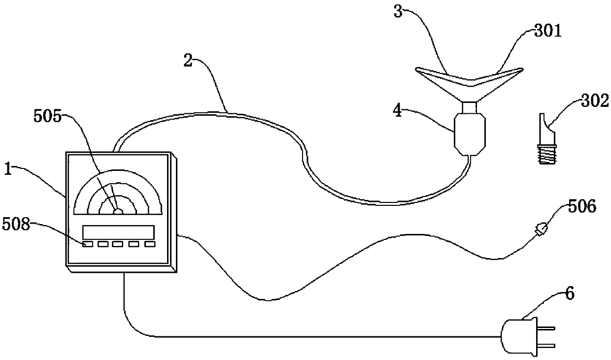
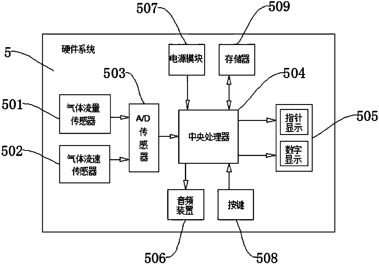
[0015] see figure 1 and figure 2 , the present invention provides a respiratory phase detection locator, which includes an instrument housing 1, a ventilation tube 2 and a breathing head 3, the instrument housing 1 is connected to one end of the ventilation tube 2, and the breathing head 3 is connected to the ventilation tube through a connector 4 2. At the other end, a hardware system 5 is provided in the instrument housing 1, and the hardware system 5 includes a gas flow sensor 501 and a gas flow velocity sensor 502 for collecting respiratory data. 501 and the data collected by the gas flow rate sensor 502 are transferred to the central processing unit 504 after conversion, and the central processing unit 504 is electrically connected to a display device 505, an audio device 506, a power module 507, buttons 508 and a memory 509, and the display device 505 Installed on the panel of the instrument housing 1 , the power module 507 is electrically connected to the plug 6 .

...


PUM


Abstract

The invention discloses a respiratory phase detection locator, comprising an instrument shell, a breather pipe and a breathing head, wherein the instrument shell is communicated with one end of the breather pipe; the breathing head is communicated with the other end of the breather pipe by means of a connector; the instrument shell is internally provided with a hardware system; the hardware systemcomprises an air flow sensor and an air flow velocity sensor which are used for acquiring breathing data; the data, acquired by the air flow sensor and the air flow velocity sensor, is converted by an analog to digital (A / D) converter and is then transmitted to a central processing unit; the central processing unit is electrically connected with a display device, an audio device, a power module,buttons and a memory. By accurately detecting the respiratory phase of a patient, the respiratory phase detection locator improves the accuracy of puncture, and avoids the phenomena that correction isrepeatedly carried out for a plurality of times and puncturing is repeatedly performed in an operation process; furthermore, by adopting dual monitoring of the air flow velocity sensor and the air flow sensor as well as dual displaying of a flow pointer dial plate and a digital display screen on a panel, the monitoring accuracy of the respiratory phase detection locator is also improved; the respiratory phase detection locator is convenient to observe and operate.

Description

technical field [0001] The invention relates to the field of medical equipment, in particular to a respiratory phase detection locator that ensures accurate puncture and avoids repeated corrections and repeated punctures during surgery. Background technique [0002] In clinical treatment, when performing puncture aspiration biopsy on the human chest and abdomen and treating tumors with microwave, radio frequency or freezing, the puncture needle must be inserted to the lesion (tumor) before suction or microwave, radio frequency and other treatments are performed. The location of the lesion (tumor) needs to be determined by CT. After the CT scan, the doctor reads the CT film and determines the puncture site according to the determined direction and angle. Since the patient is breathing continuously, even if the patient is asked to hold his breath, every breath will It is impossible to be at the same time phase, so the patient’s respiratory phase during the CT scan and the pati...

Claims


Application Information

Patent Timeline
Patent Type & Authority Applications(China)
IPC IPC(8): A61B5/08
CPCA61B5/08
Inventor 李麟荪施海彬
Owner 上海墨汇机器人科技有限公司
Learn More