Material storage tank heat washing machine

A storage tank and hot washing machine technology, applied in the field of building construction equipment and storage tank hot washing machine, can solve the problems of narrow cleaning area, poor cleaning effect, small cleaning force, etc., and achieve high cleaning force and good cleaning effect. , The effect of cleaning a wide area

Inactive Publication Date: 2018-03-06
李秀青
View PDF1 Cites 3 Cited by
  • Summary
  • Abstract
  • Description
  • Claims
  • Application Information

AI Technical Summary

Problems solved by technology

[0005] The purpose of the present invention is to overcome the defects and problems existing in the prior art that the cleaning area is narrow, the cleaning force is small, and the cleaning effect is poor, and to provide a storage tank with a wide cleaning area, a large cleaning force, and a good cleaning effect. Tank hot washing machine

Method used


Image

  • Material storage tank heat washing machine
  • Material storage tank heat washing machine

Examples


Embodiment Construction

[0026] The present invention will be described in further detail below in conjunction with the accompanying drawings and specific embodiments.

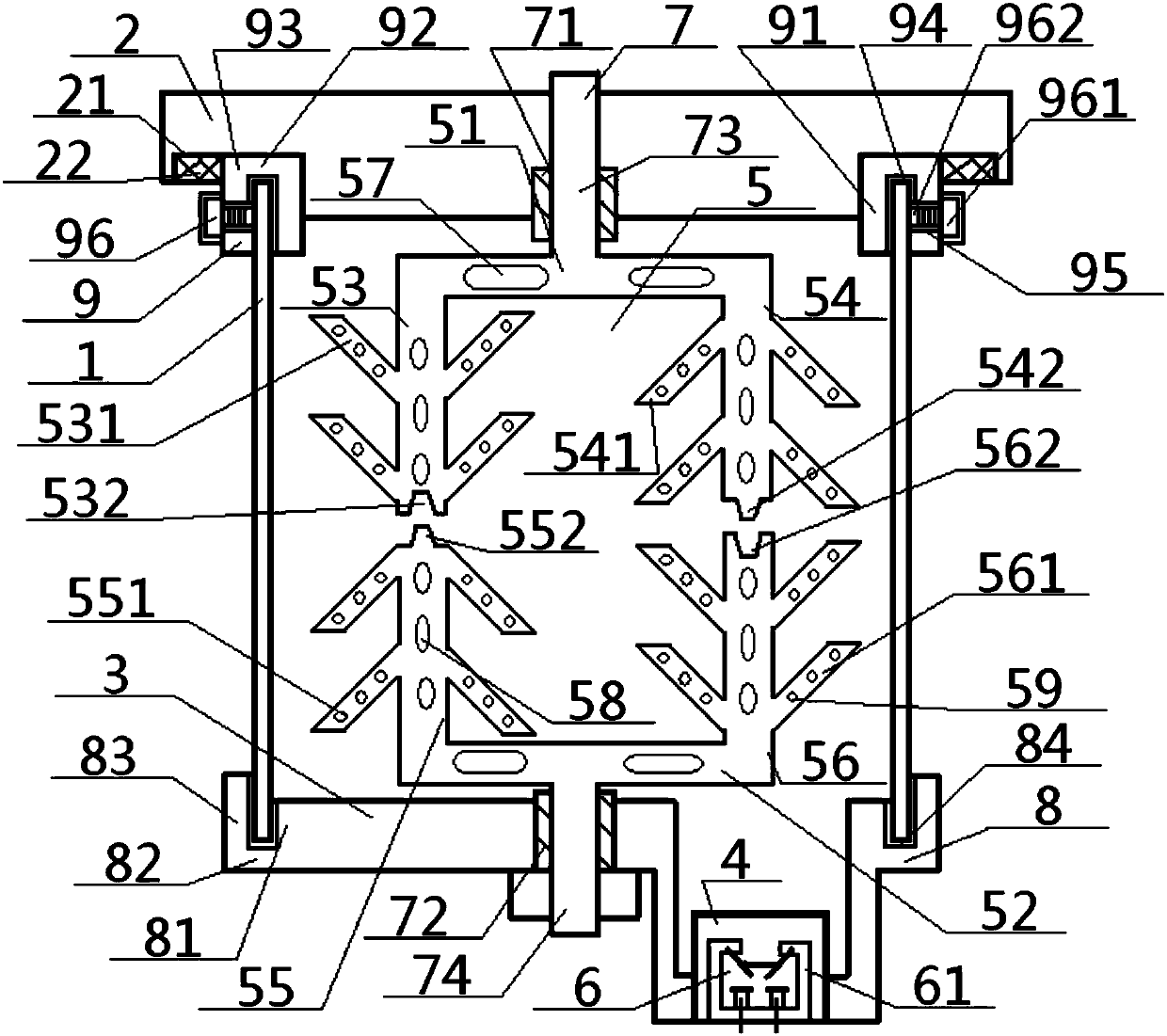
[0027] see Figure 1 to Figure 2 , a thermal washing machine for a storage tank, comprising a storage tank body 1 and a cleaning main device 5, the cleaning main device 5 is located inside the storage tank body 1, and there is a cleaning device passing through the middle of the cleaning main device 5 spindle 7;

[0028] The middle part of the cleaning main shaft 7 is positioned at the inside of the cleaning main device 5, and the two ends of the cleaning main shaft 7 are connected with the upper fixed bearing 71 and the lower fixed bearing 72 respectively, and the upper fixed bearing 71 is positioned at the inside of the middle part of the upper connecting seat 2, and the lower The fixed bearing 72 is located inside the middle part of the lower connecting seat 3, and the two ends of the lower connecting seat 3 are provided with lower...


PUM


Abstract

A thermal washing machine for storage tanks, in which the cleaning spindle drives the upper flat air pipe, the lower flat air pipe, the upper left vertical pipe, the upper right vertical pipe, the lower left vertical pipe, and the lower right vertical pipe to move up and down or rotate in situ to clean the cleaning liquid. Stirring, at the same time, large pores, medium pores, and small pores spray high-temperature gas outward in the state of rotation, which has the functions of stirring enhancement and providing heat source. The upper connecting seat and the lower connecting seat provide the firmness of the connection, and the lower connecting seat The temperature measuring sensor set on the top monitors the temperature in the material storage tank. This design not only has a wider cleaning area, greater cleaning force, and better cleaning effect, but also has strong adjustability, high stability, and good heating effect.

Description

technical field [0001] The invention relates to building construction equipment, which belongs to the field of construction, and in particular to a heat storage tank washing machine, which is particularly suitable for enlarging the cleaning area, enhancing the cleaning force and improving the cleaning effect. Background technique [0002] Commonly used vehicles carrying cement tanks are also called bulk cement trucks, powder tank trucks, tank trucks or powder material transport vehicles. They are mainly composed of vehicle chassis and storage tanks. They are suitable for fly ash, cement, lime powder, ore powder, The bulk transportation of powdery dry matter such as granular alkali is mainly used in cement plants, cement warehouses and construction sites, especially on construction sites. [0003] The authorized announcement number is CN205989693U, and the invention patent issued on March 1, 2017 discloses a cement tank truck flushing tank, which includes a tank body, an anti...

Claims


Application Information

Patent Timeline
Patent Type & Authority Applications(China)
IPC IPC(8): B08B9/08B08B3/10
CPCB08B9/0817B08B3/10B08B9/0804
Inventor 李秀青
Owner 李秀青
Why Eureka
Try Eureka