
Semi-automatic clamp loading machine

A semi-automatic, clip technology, used in assembly machines, metal processing, metal processing equipment, etc., can solve problems such as inability to meet mass production of products, low assembly efficiency, and waste of labor.

Inactive Publication Date: 2018-03-06
常州叶晗电子科技有限公司
View PDF0 Cites 2 Cited by
  • Summary
  • Abstract
  • Description
  • Claims
  • Application Information

AI Technical Summary

Problems solved by technology

[0002] The clips commonly used by people nowadays are generally hinged by the upper clip and the lower clip, and springs are installed in the upper clip and the lower clip. In the middle of the clip, in the production process, the current general practice is to use manual assembly work. Since these assembly tasks require a large force to be completed, the operator is prone to fatigue after working for a long time, and the assembly efficiency is low and labor is wasted. Unable to meet the needs of mass production of products

Method used


Image

  • Semi-automatic clamp loading machine

Examples


Embodiment Construction

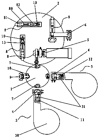
[0011] The present invention will be further described below in conjunction with accompanying drawing, see attached drawing figure 1 , a semi-automatic clamping machine, which includes a first turntable 1, a second turntable 2 adjacent to the first turntable 1, two feeding systems 3, two first manipulators 4, a linear cylinder 9, at least 4 along the first turntable 1 press-fitting jig 7 evenly distributed in the circumferential direction, at least 4 assembly jigs 8 evenly distributed along the circumferential direction of the second turntable 2, the second manipulator 5, the third manipulator 6, and the drive to rotate the first turntable 1 and the second turntable 2 The power unit, the second manipulator 5, the linear cylinder 9 and the two first manipulators 4 are sequentially arranged beside the first turntable 1 and correspond to the pressing fixtures 7 one by one, the feeding system 3 is set correspondingly to the first manipulator 4, and the second The manipulator 5 and...


PUM


Abstract

The present invention relates to the technical field of industrial assembly devices, in particular to a semi-automatic clamping machine, which includes a first turntable, a second turntable, a feeding system, a first manipulator, a linear cylinder, and at least four press-fitting machines evenly distributed along the circumference of the first turntable. Fixtures, at least 4 assembly fixtures evenly distributed along the circumference of the second turntable, the second manipulator, the third manipulator, the power device that drives the first turntable and the second turntable to rotate, the second manipulator, the linear cylinder and the first manipulator are arranged in sequence Next to the first turntable and one-to-one correspondence with the pressing fixture, the feeding system is set corresponding to the first manipulator, the second manipulator and the third manipulator are in one-to-one correspondence with the assembly fixture, and the third manipulator is set next to the second turntable; the present invention It has the effects of high degree of automation, improving production efficiency and saving labor.

Description

technical field [0001] The invention relates to the technical field of industrial assembly devices, in particular to a semi-automatic clamping machine. Background technique [0002] The clips commonly used by people nowadays are generally hinged by the upper clip and the lower clip, and springs are installed in the upper clip and the lower clip. In the middle of the clip, in the production process, the current general practice is to use manual assembly work. Since these assembly tasks require a large force to be completed, the operator is prone to fatigue after working for a long time, and the assembly efficiency is low and labor is wasted. It cannot meet the needs of mass production of products. Contents of the invention [0003] The purpose of the present invention is to provide a semi-automatic clamping machine for the deficiencies of the prior art, which has the effects of high automation, improved production efficiency and labor saving. [0004] To achieve the above...

Claims


Application Information

Patent Timeline
IPC IPC(8): B23P21/00
CPCB23P21/006B23P19/001
Inventor 刘文昭
Owner 常州叶晗电子科技有限公司
Learn More