Prefabricated component of concrete component
A technology of prefabricated components and concrete, applied in the direction of mold auxiliary parts, molds, etc., can solve the problems affecting the construction efficiency and the quality of concrete pouring, and achieve the effect of eliminating grout leakage and ensuring quality
- Summary
- Abstract
- Description
- Claims
- Application Information
AI Technical Summary
Problems solved by technology
Method used
Image
Examples
Embodiment 1
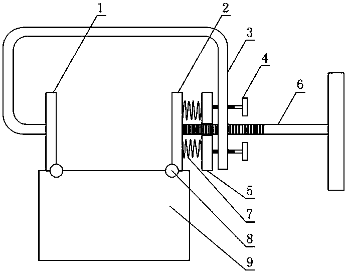
[0027] Such as figure 1 As shown, a prefabricated component of a concrete component includes a panel frame 3, a fixed formwork 1 and a movable formwork 2, the fixed formwork 1 is fixed on the panel frame 3, the fixed formwork 1 and the movable formwork 2 are in a positive relationship, and the fixed formwork 1 There is a gap for clamping the template between the movable formwork 2, and also includes a pressure plate bolt threaded on the plate frame 3, the axis of the pressure plate bolt is located in the width direction of the gap, and the end of the pressure plate bolt is connected to the The outer contact of movable formwork 2 also includes spring 7 and anti-loosening bolt 4, and described anti-loosening bolt 4 is threadedly connected on the plate frame 3, and the axis of anti-loosening bolt 4 is parallel to the axis of hold-down bolt 6, and described spring 7 is arranged between the movable formwork 2 and the anti-loosening bolt 4. In the working state, the two ends of the ...
Embodiment 2
[0033] The present embodiment is further limited on the basis of embodiment 1, as figure 1 As shown, as an easy-to-implement concrete solution, the panel frame 3 is U-shaped, and the fixed formwork 1 and the movable formwork 2 are located on different sides of the open end of the panel frame 3 respectively. In the above structure, the anti-loosening bolt 4 and the compression bolt 6 can be screwed to one side of the plate frame 3 at the same time, so as to complete the compression of the spring 7 and the adjustment of the position of the movable formwork 2 .
[0034] Since the shrinkage of the concrete mortar is smaller than the width of the gap between the fixed formwork 1 and the movable formwork 2, in order to facilitate the anti-leakage grout effect, it is preferable to select a spring with a larger elastic coefficient, and the spring 7 is composed of a plurality of disc-shaped A spring set formed by stacking springs.
[0035] In order to prevent the movable template 2 fr...
Embodiment 3
[0037] The present embodiment further limits the present invention on the basis of embodiment 1, as figure 1 As shown, in order to prevent the movable formwork 2 from being too skewed under the elastic stress of the spring 7 and to facilitate the forming quality of the prefabricated component, the springs 7 are multiple, and the multiple springs 7 are annular and evenly spaced relative to the axis of the compression bolt 6. The cloth also includes an anti-loosening plate 5 that fits in a gap with the compression bolt 6, the anti-loosening plate 5 is arranged between the spring 7 and the anti-loosening bolt 4, and the anti-loosening plate 5 is used for the spring 7 and the anti-loosening bolt 4 Stress transmission between them, the anti-loosening bolt 4 is more than one, and different anti-loosening bolts 4 are arranged on different sides of the compression bolt 6 .
PUM
 Abstract
Description
Claims
Application Information
 - R&D
- Intellectual Property
- Life Sciences
- Materials
- Tech Scout
- Unparalleled Data Quality
- Higher Quality Content
- 60% Fewer Hallucinations
Browse by: Latest US Patents, China's latest patents, Technical Efficacy Thesaurus, Application Domain, Technology Topic, Popular Technical Reports.
© 2025 PatSnap. All rights reserved.Legal|Privacy policy|Modern Slavery Act Transparency Statement|Sitemap|About US| Contact US: help@patsnap.com

