
Fusion-splicing clamping device for C lens

A clamping and lens technology, which is applied to other home appliances, optical components, home appliances, etc., can solve the problems of coating surface damage, trouble, low efficiency, etc., and achieve the effect of low cost, convenient and efficient operation, and strong operability

Pending Publication Date: 2018-03-06
WUHAN RAYCUS FIBER LASER TECHNOLOGY CO LTD
View PDF13 Cites 0 Cited by
  • Summary
  • Abstract
  • Description
  • Claims
  • Application Information

AI Technical Summary

Problems solved by technology

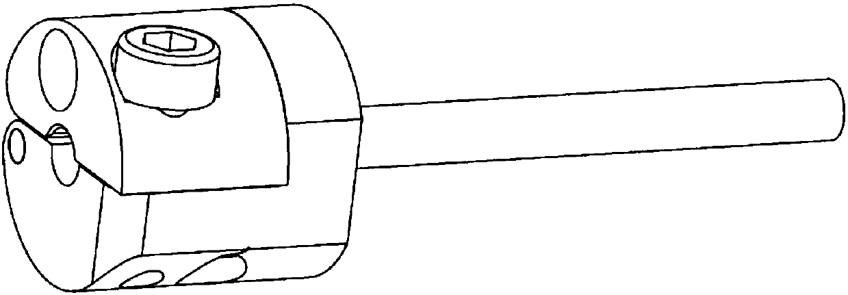
There are two common methods at present. The first method is to put the C lens into the small hole of the clamping device and press it with a set screw, such as figure 2 As shown, the disadvantage of this method is that it is easy to cause damage to the coating surface, because the C lens and the installation hole are precisely matched, and it needs to be adjusted before being installed, and the coating surface will inevitably touch the edge of the hole and be damaged; the second One method is to use an independent gland to compress the C lens through screws, such as image 3 As shown, the disadvantage of this method is that the operation of pressing the C lens by the gland and loosening and taking out the C lens is very troublesome and the efficiency is low.

Method used


Image

  • Fusion-splicing clamping device for C lens
  • Fusion-splicing clamping device for C lens
  • Fusion-splicing clamping device for C lens

Examples


Embodiment Construction

[0025] The present invention will be further described with reference to the drawings.

[0026] At present, there are two common methods. The first method is to put the C lens into the small hole of the holding device and press it with a set screw, such as figure 2 As shown, the drawback of this method is that it is easy to cause damage to the coating surface, because the C lens and the mounting hole are precisely matched, and the centering adjustment is required before installation, and the coating surface will inevitably touch the edge of the orifice and be damaged; second One method is to use a separate cover to compress the C lens with a screw, such as image 3 As shown, the disadvantage of this method is that the operations of pressing the C lens by pressing the cap and releasing the C lens are very troublesome and low in efficiency.

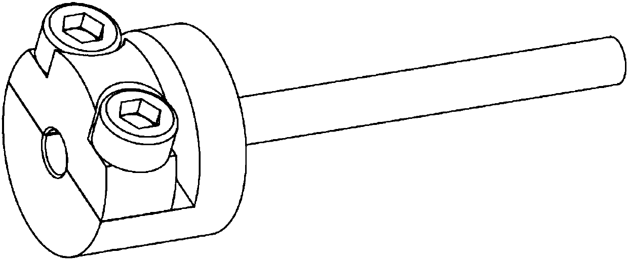
[0027] Such as figure 1 , Figure 4 , Figure 5 As shown, a C lens welding device includes a connecting rod 100, a clamping base 101, a gland 1...


PUM


Abstract

The invention relates to a fusion-splicing device for a C lens. The fusion-splicing device comprises a connection rod, a clamping base, a gland, a pin shaft, a hexagon socket head cap screw and two cylindrical magnets. The fusion-splicing device is characterized in that the connection rods and the clamping base are connected to form a whole; the clamping base is connected with the gland through the pin; the gland can be freely overturned around the pin shaft; the hexagon socket head cap screw tightly locks the clamping base and the gland; one cylindrical magnet is mounted and fixedly arrangedin each interior of the clamping base and the gland. The two cylindrical magnets in the interiors of the clamping base and the gland repel each other; when the hexagon socket head cap screw is unscrewed, the gland can be loosened automatically; after the gland is loosened, the C lens can be put in or taken out. According to a fusion-splicing clamping device for the C lens, which is provided by theinvention, the opening and the closing of a mounting hole can be controlled under the action of the repelling force of the cylindrical magnets by utilizing the gland and cooperating with the screwingoperation of the screw and not only is the coated surface of the C lens prevented from being damaged but also the loading-in and taking-out operation efficiency of the C lens is improved.

Description

Technical field [0001] The invention relates to a C lens welding clamping device, which is a new structure for welding C lens in the field of laser device manufacturing. Background technique [0002] With the mass production of C lenses, laser device manufacturers are paying more and more attention to welding methods. C lens generally cannot be directly fixed in the welding machine for welding operation. Before welding, it needs to be clamped by the device, and then the device is installed in the welding machine for welding operation. The clamping direction is that the light-emitting surface of the C lens coating is inside the clamping device, and the other end is exposed outside the device. At present, there are two common methods. The first method is to put the C lens into the small hole of the holding device and press it with a set screw, such as figure 2 As shown, the drawback of this method is that it is easy to cause damage to the coating surface, because the C lens and th...

Claims


Application Information

Patent Timeline
Patent Type & Authority Applications(China)
IPC IPC(8): B29C65/78B29L11/00
CPCB29C65/7841B29L2011/0016
Inventor 赵文利黄中亚
Owner WUHAN RAYCUS FIBER LASER TECHNOLOGY CO LTD
Learn More