Machining device and method for inclined disc face of rotary motor shell of excavator
A rotary motor and processing device technology, applied in the field of mechanical processing, can solve the problems of low processing efficiency, high processing difficulty, computerized turning center of the machine tool, and cumbersome starting point of the turning center and processing, so as to achieve simple processing, reduce processing difficulty, and debug Convenient and fast effect
- Summary
- Abstract
- Description
- Claims
- Application Information
AI Technical Summary
Problems solved by technology
Method used
Image
Examples
Embodiment 1
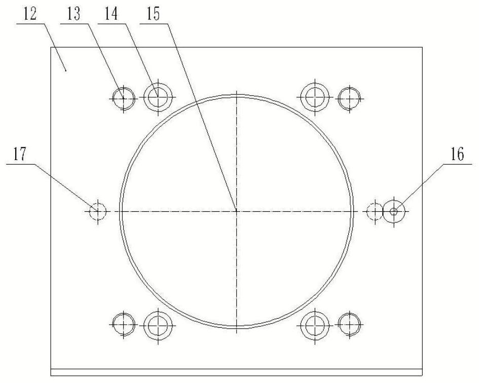
[0045] Such as figure 1 As shown, a processing device for the swash plate surface of the rotary motor housing of an excavator includes a tooling plate 12, and the tooling plate 12 is provided with a central hole 15, a plurality of counterbore holes 14, a plurality of threaded holes 13, and a plurality of pins. Holes 17, ball sockets 16 and steel balls 21, the central hole 15 is used to place the rotary motor housing 1 to be processed, the plurality of counterbore holes 14 are arranged circumferentially along the central hole 15, and the plurality of threaded holes 13 Corresponding to the plurality of counterbore holes 14 and the threaded hole 13 is arranged on the side of the counterbore hole 14 away from the center hole 15, the plurality of pin holes 17 are arranged along the circumference of the center hole 15, and the ball socket 16 is arranged On the side of the pin hole 17 away from the central hole 15, the steel ball 21 is arranged in the ball socket 16;
[0046] It als...
Embodiment 2
[0062] On the basis of Example 1, such as Figure 1-4 As shown, a method for processing the swash plate surface of the excavator slewing motor housing, using the processing device for the swash plate surface of the excavator slewing motor housing, includes the following steps:
[0063] S1: Draw the distance in the x-axis direction and the y-axis direction from the intersection point 11 of the center line of the swash plate surface and the swash plate surface to the center 22 of the steel ball 21 in the two-dimensional diagram:
[0064] Respectively determine the intersection point 10 of the center line of the swash plate surface and the swash plate surface to be processed as A and the intersection point 11 of the center line of the swash plate surface and the swash plate surface as B, use the coordinate probe of the horizontal machining center to find the center 22 of the steel ball 21 as C, Calculated, the distance X from C to B in the x-axis direction, and the distance Y fro...
Embodiment 3
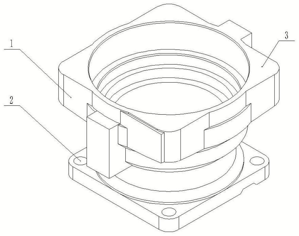
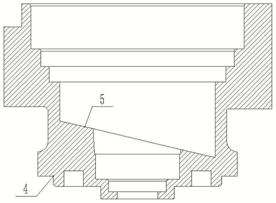
[0078] On the basis of Example 1 and Example 2, as Figure 5 As shown, the angle between the center line 8 of the swash plate surface and the center line 7 of the rotary motor housing is 13.2°±0.1°, the vertical distance between the center line of the swash plate surface and the intersection point 11 of the swash plate surface and the plane 3 of the shell is 134.14±0.1mm, and the swash plate surface The linear reference distance between the intersection point 11 of the center line and the swash plate surface and the intersection point 9 of the center line 9 of the rotary motor housing and the swash plate surface 6 is 6.43 mm. The distance between the swash plate surface 5 to be processed and the swash plate surface 6 is 5 mm. The degree requirement is 0.1; for details, see Figure 5 As shown, the specific steps are as follows:
[0079] S1: Draw the distance in the X direction of the center line 22 of the steel ball 21 in the ball socket 16 on the tooling plate 12 and the inte...
PUM
 Abstract
Description
Claims
Application Information
 - R&D
- Intellectual Property
- Life Sciences
- Materials
- Tech Scout
- Unparalleled Data Quality
- Higher Quality Content
- 60% Fewer Hallucinations
Browse by: Latest US Patents, China's latest patents, Technical Efficacy Thesaurus, Application Domain, Technology Topic, Popular Technical Reports.
© 2025 PatSnap. All rights reserved.Legal|Privacy policy|Modern Slavery Act Transparency Statement|Sitemap|About US| Contact US: help@patsnap.com


