
Multifunctional high-altitude working platform

An aerial work platform, multi-functional technology, applied in the direction of lifting device, portable lifting device, hoisting device, etc., can solve the problems of few types of aerial work platforms, inconvenient movement and operation, frequent adjustment and positioning, etc. The effect of weight reduction and low cost

Inactive Publication Date: 2018-03-06
刘晓东
View PDF0 Cites 6 Cited by
  • Summary
  • Abstract
  • Description
  • Claims
  • Application Information

AI Technical Summary

Problems solved by technology

[0002] With the development of production technology and social economy, the requirements for the maintenance and overhaul equipment of the power system are becoming more and more stringent. When working at adjacent high altitudes, the adjustment and positioning are frequent, which brings inconvenience to maintenance. The existing relatively advanced mobile cranes are vehicle-mounted. It is extremely inconvenient to enter and stop work, and there are safety hazards in this way at the work site with limited space. Therefore, there is an urgent need for a low-cost, simple structure, small work space, movable aerial work platform with hoisting function

Method used


Image

  • Multifunctional high-altitude working platform
  • Multifunctional high-altitude working platform

Examples


Embodiment 1

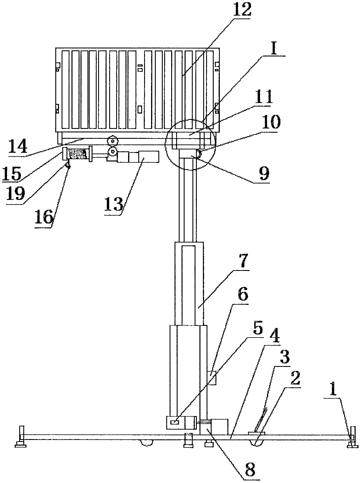
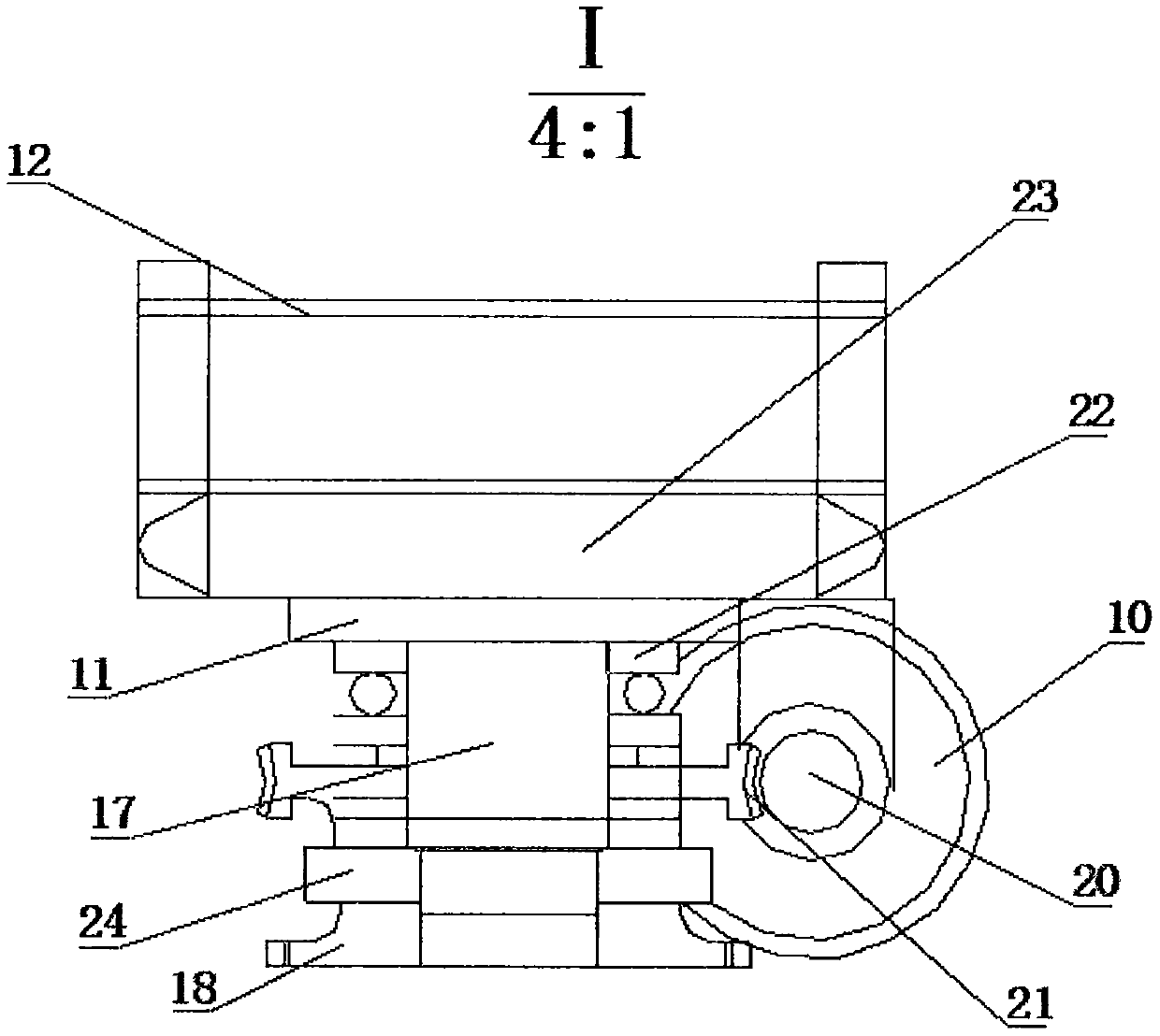
[0016] Such as figure 1 and figure 2 As shown, a multifunctional aerial work platform includes a chassis 4, a leg 1 is arranged under the chassis 4, a wheel 2 is arranged under the chassis 4, and the upper part of the right side wheel 2 is connected with The reversing rod 3, the center of the chassis 4 is provided with a motor A5, a hydraulic pump 8 and a telescopic column 7, the telescopic column 7 is provided with an electric control cabinet 6, and the telescopic column 7 is a secondary hydraulic support rod , the cylinder body of the telescopic column 7 is connected to the chassis 4, the top of the secondary pole of the telescopic column 7 is connected with a flange 25, and a worm gear 21 is arranged between the crossbeam 11 and the secondary pole Mechanism 9, a protective railing 12 is arranged above the beam 11, a reel support 14 is connected below the beam 11, a motor C13 is connected below the reel support 14, and the output shaft of the motor C13 is connected to The...

Embodiment 2

[0019] Such as figure 1 and figure 2 As shown, a multifunctional aerial work platform includes a chassis 4, a leg 1 is arranged under the chassis 4, a wheel 2 is arranged under the chassis 4, and the upper part of the right side wheel 2 is connected with The reversing rod 3, the center of the chassis 4 is provided with a motor A5, a hydraulic pump 8 and a telescopic column 7, the telescopic column 7 is provided with an electric control cabinet 6, and the telescopic column 7 is a secondary hydraulic support rod , the cylinder body of the telescopic column 7 is connected to the chassis 4, the top of the secondary pole of the telescopic column 7 is connected with a flange 25, and a worm gear 21 is arranged between the crossbeam 11 and the secondary pole Mechanism 9, a protective railing 12 is arranged above the beam 11, a reel support 14 is connected below the beam 11, a motor C13 is connected below the reel support 14, and the output shaft of the motor C13 is connected to The...


PUM


Abstract

The invention relates to a multi-functional high-altitude work platform, which includes a chassis, and its working principle is to put the chassis in a horizontal position according to the assembled support, start the motor A to adjust the telescopic column to adjust the workbench to a suitable position, and start the motor C to drive The reel rotates, the steel wire rope is used to lift the heavy object, and the motor B drives the worm gear mechanism to rotate to make the workbench face to a suitable working position. The present invention adopts the combination of telescopic column, reel and worm gear. It has the advantages of multiple functions, low cost, flexible operation and large operating range.

Description

technical field [0001] The invention belongs to the field of hoisting machinery, and in particular relates to a multifunctional aerial work platform. Background technique [0002] With the development of production technology and social economy, the requirements for the maintenance and overhaul equipment of the power system are becoming more and more stringent. When working at adjacent high altitudes, the adjustment and positioning are frequent, which brings inconvenience to maintenance. The existing relatively advanced mobile cranes are vehicle-mounted. It is extremely inconvenient to enter and stop work, and there are safety hazards in this way at the work site with limited space. Therefore, there is an urgent need for a low-cost, simple structure, small work space, movable aerial work platform with hoisting function. Contents of the invention [0003] The purpose of the present invention is to overcome the deficiencies of the prior art, and provide a low cost, simple s...

Claims


Application Information

Patent Timeline
Patent Type & Authority Applications(China)
IPC IPC(8): B66F11/04B66D3/18
CPCB66F11/046B66D3/18B66F2700/05
Inventor 刘晓东
Owner 刘晓东
Learn More