Oil water separator diffuser cap extension to filter cartridge

A filter and filter cartridge technology, applied in the direction of filtration separation, membrane filter, immiscible liquid separation, etc.

Active Publication Date: 2018-03-06
INGERSOLL RAND IND U S INC
View PDF11 Cites 7 Cited by
  • Summary
  • Abstract
  • Description
  • Claims
  • Application Information

AI Technical Summary

Problems solved by technology

Some existing systems have various disadvantages with respect to certain applications

Method used


Image

  • Oil water separator diffuser cap extension to filter cartridge
  • Oil water separator diffuser cap extension to filter cartridge
  • Oil water separator diffuser cap extension to filter cartridge

Examples


Embodiment Construction

[0012] For the purposes of promoting an understanding of the principles of the invention, reference will now be made to the embodiments illustrated in the drawings, and specific language will be used to describe the same. It should be understood, however, that no limitation of the scope of the invention is thereby intended. Any alterations and further modifications in the described embodiments, as well as any further applications of the principles of the invention as described herein, are to be contemplated as would normally occur to one skilled in the art to which the invention pertains.

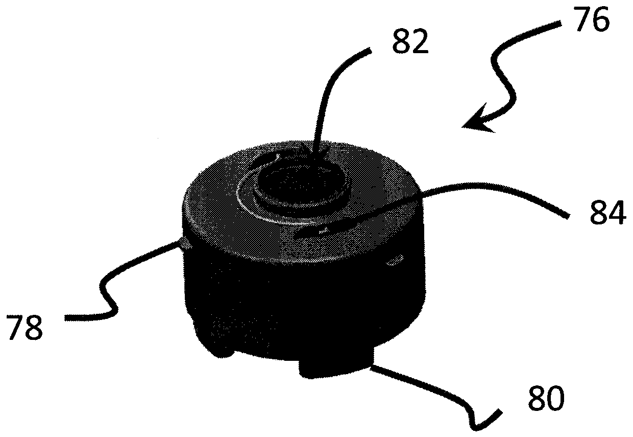
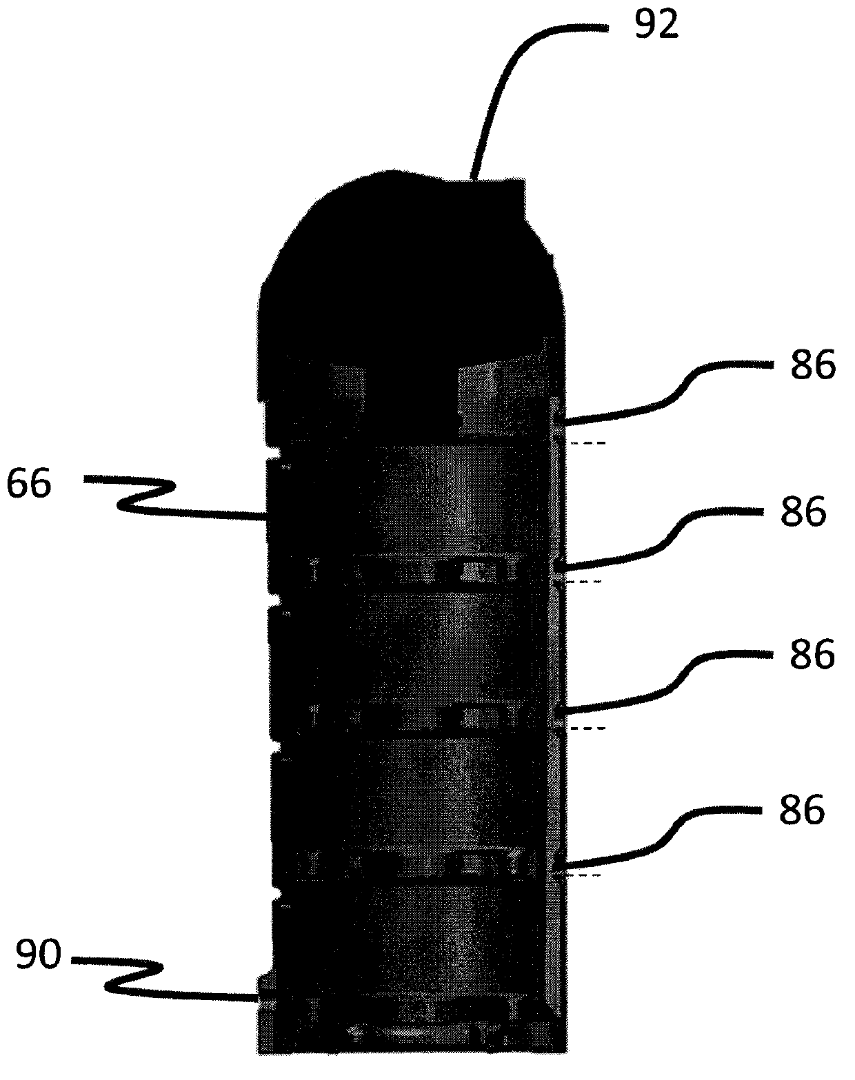
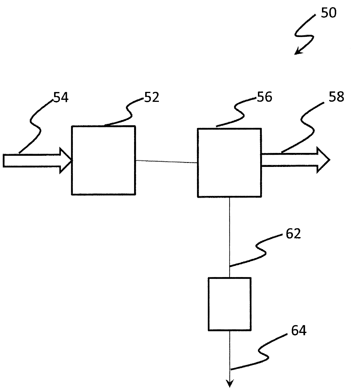
[0013] see figure 1 , discloses a compressor system 50 having a compressor 52 configured to receive and compress a gaseous composition 54 including a target gas (eg, air) and an undesired vapor (eg, water vapor). Compressor 52 may take a variety of forms, such as, but not limited to, an oil-filled screw compressor, although other forms are also contemplated. Compressor system 50 also incl...


PUM


Abstract

During the process of compressing air, atmospheric air along with water vapor and airborne contaminants are ingested into the air compressor. Many of these compressors utilize oil for lubrication, sealing and cooling. A compressor system utilizes drain valves to remove the condensate that accumulates in the system which are typically located on the compressor, moisture separators, coalescing filters, receivers, dryers, and drip legs. While the drain valves successfully remove the condensate, this condensate is now contaminated with lubricant. The compressor system also includes a filter for the removal of lubricant from the condensed water so that the water can be discharged to sewer. The filter is arranged to house a series of vertically stacked filter cartridges, each cartridge structured to pass fluid flow to the other cartridge. The housing is connected to the filter cartridges via a variable length pipe extension dependent on the number of filter cartridges used in an application.

Description

technical field [0001] The present invention relates generally to air compressor system filters, and more particularly, but not exclusively, to filter and housing structures for removing oil from condensate produced by air compressor systems. Background technique [0002] It remains an area of ​​interest to provide filtration systems for removing lubricant from condensate produced by compressor systems. Some existing systems have various disadvantages with respect to certain applications. Therefore, further contributions are still required in this field. Contents of the invention [0003] One embodiment of the present invention is a unique system that provides flexibility in how many filter cartridges for oil removal from air compressor condensate can be used in a given filter housing. Other embodiments include devices, systems, apparatus, hardware, methods, and combinations for varying the number of filter cartridges through the use of pipe extensions. Other embodiment...

Claims


Application Information

Patent Timeline
Patent Type & Authority Applications(China)
IPC IPC(8): C02F1/40B01D17/02B01D17/12B01D53/26B01D53/00
CPCB01D17/02B01D17/08B01D17/12B01D53/002B01D53/265C02F1/40B01D2258/06B01D35/12B01D24/007B01D24/02B01D29/56B01D29/58B01D29/96B01D35/02C02F1/001B01D24/10B01D24/008B01D2201/24B01D2201/302B01D2201/40C02F2101/32C02F2201/007
Inventor J.雅各普D.罗森萨尔
Owner INGERSOLL RAND IND U S INC
Why Eureka
Try Eureka