Cast-in-situ lightweight concrete structure based on spiral steel piles and construction method thereof

A light-weight concrete and construction method technology, which is applied in the direction of foundation structure engineering, sheet pile walls, roads, etc., can solve the problems of easy differential settlement and low cohesion, and achieve internal and external stability problems, Increased stability, low density effect

Pending Publication Date: 2018-03-06
GUYUAN CHENTONG TECH DEV CO LTD
View PDF8 Cites 0 Cited by
  • Summary
  • Abstract
  • Description
  • Claims
  • Application Information

AI Technical Summary

Problems solved by technology

However, the cohesion between lightweight concrete and granular materials is low, and differential settlement is prone to occur, resulting in water softening of the structure, which in turn leads to problems with the internal and external stability of the structure

Method used


Image

  • Cast-in-situ lightweight concrete structure based on spiral steel piles and construction method thereof
  • Cast-in-situ lightweight concrete structure based on spiral steel piles and construction method thereof

Examples


Embodiment 1

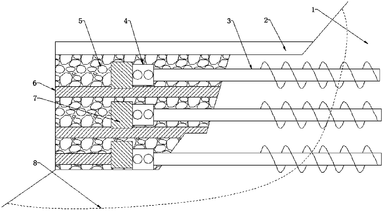
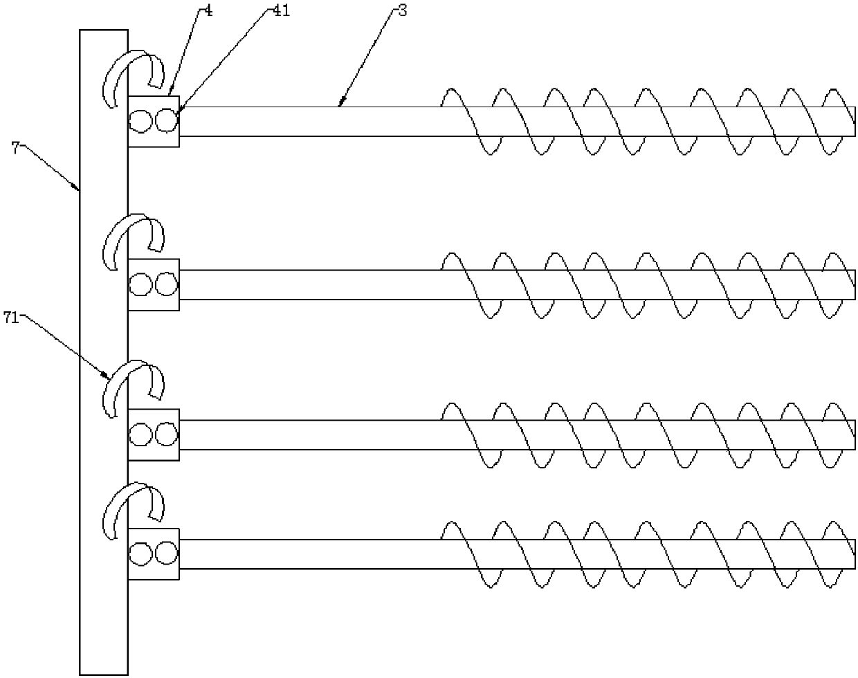
[0030] The present invention is based on a cast-in-situ lightweight concrete structure supported by spiral steel piles, which is characterized in that it comprises a lightweight concrete 5 poured on the side of the potential landslide layer 8 of the original hillside 1, and a plurality of connecting rods are arranged in the lightweight concrete 5 7. The connecting rod 7 is connected with a plurality of upside-down quick joints 4, and each upside-down quick joint 4 is connected to a spiral steel pile 3 with spiral blades, and the spiral blades on the spiral steel pile 3 pass through the potential landslide Layer 8.

[0031] Preferably, the connecting rod 7 is located in the lightweight concrete 5 on the side close to the potential landslide layer 7.

[0032] Preferably, the lightweight concrete 5 is further provided with a reinforcement layer 6 which is a high-strength geogrid or a galvanized metal mesh, and the reinforcement layer 6 is distributed at intervals in the vertical direc...

Embodiment 2

[0051] The present invention is based on a cast-in-situ lightweight concrete structure supported by spiral steel piles, which is characterized in that it comprises a lightweight concrete 5 poured on the side of the potential landslide layer 8 of the original hillside 1, and a plurality of connecting rods are arranged in the lightweight concrete 5 7. The connecting rod 7 is connected with a plurality of upside-down quick joints 4, and each upside-down quick joint 4 is connected to a spiral steel pile 3 with spiral blades, and the spiral blades on the spiral steel pile 3 pass through the potential landslide Layer 8.

[0052] Preferably, the connecting rod 7 is located in the lightweight concrete 5 on the side close to the potential landslide layer 7.

[0053] Preferably, the lightweight concrete 5 is further provided with a reinforcement layer 6 which is a high-strength geogrid or a galvanized metal mesh, and the reinforcement layer 6 is distributed at intervals in the vertical direc...

Embodiment 3

[0072] The present invention is based on a cast-in-situ lightweight concrete structure supported by spiral steel piles, which is characterized in that it comprises a lightweight concrete 5 poured on the side of the potential landslide layer 8 of the original hillside 1, and a plurality of connecting rods are arranged in the lightweight concrete 5 7. The connecting rod 7 is connected with a plurality of upside-down quick joints 4, and each upside-down quick joint 4 is connected to a spiral steel pile 3 with spiral blades, and the spiral blades on the spiral steel pile 3 pass through the potential landslide Layer 8.

[0073] Preferably, the connecting rod 7 is located in the lightweight concrete 5 on the side close to the potential landslide layer 7.

[0074] Preferably, the lightweight concrete 5 is further provided with a reinforcement layer 6 which is a high-strength geogrid or a galvanized metal mesh, and the reinforcement layer 6 is distributed at intervals in the vertical direc...


PUM

PropertyMeasurementUnit
diameteraaaaaaaaaa
diameteraaaaaaaaaa
diameteraaaaaaaaaa

Abstract

The invention discloses a cast-in-situ lightweight concrete structure based on spiral steel piles and a construction method thereof, belonging to the technical field of slope roadbed strengthening, and solving the filling problem of high roadbeds of a high speed railway or a high way on a steep slope. The concrete structure comprises lightweight concrete casted on the side surface of a potential landslide layer of an original slope, wherein an upper structure is arranged at the upper end of the lightweight concrete, connecting rods are arranged at one end, close to the potential landslide layer, of the lightweight concrete, and a plurality of inversely-hung rapid joints are arranged on the connecting rods and are connected with spiral steel piles. According to the concrete structure, the advantages that cast-in-situ lightweight concrete is low in density, high in strength and low in construction disturbance and can be vertically casted can be adequately utilized, and meanwhile, the advantages that the spiral steel pile is wide in applicability, small in work plane, high in construction speed and good in durability are utilized, so that the stability of the original slope is improved, and the integrity of a lightweight concrete embankment and the original slope is improved.

Description

Technical field [0001] The invention relates to the technical field of slope roadbed reinforcement, and more specifically to a method for strengthening cast-in-place lightweight concrete based on spiral steel piles. Background technique [0002] With the expansion of the transportation network, there will be problems in building high-speed railways and highway subgrades on steep slopes. As a new type of filler, cast-in-place lightweight concrete has the advantages of light weight, high strength, fast construction, and good durability. It is gradually applied to the filling of steep slopes and high roads to solve the problems of heavy weight and high cost of conventional fillers. However, the adhesion of lightweight concrete and bulk materials is low, and differential settlement is prone to occur, which leads to softening of the structure by ingress of water, which in turn causes problems in the internal and external stability of the structure. Therefore, there is an urgent need ...

Claims


Application Information

Patent Timeline
Patent Type & Authority Applications(China)
IPC IPC(8): E01C3/04E02D5/28E02D5/56
CPCE01C3/04E02D5/28E02D5/56
Inventor 苏谦赵文辉
Owner GUYUAN CHENTONG TECH DEV CO LTD
Why Eureka
Try Eureka