
Convenient and fast type roadbed tamping machine

A tamping machine, a portable technology, applied in infrastructure engineering, soil protection, construction, etc., can solve the problems of difficult disassembly and maintenance, increased working time, and increased road construction costs, so as to achieve convenient disassembly and maintenance , improve the overall progress, improve the effect of maintenance efficiency

Inactive Publication Date: 2018-03-06
张伟萍
View PDF8 Cites 4 Cited by
  • Summary
  • Abstract
  • Description
  • Claims
  • Application Information

AI Technical Summary

Problems solved by technology

[0002] In road construction, in order to improve the pressure resistance of the road surface, the sand and gravel of the roadbed are generally tamped. The traditional tamping uses a manually moved vibratory compactor or a large hydraulic compactor. The manually moved vibratory compactor not only requires A large amount of labor, and the tamping accuracy is not high, the speed is slow, the tamping quality is poor, the working time is increased, the action surface is small, the energy consumption is relatively large through large-scale hydraulic tamping, the equipment utilization rate is low, and the construction cost of the road is increased. In addition, the traditional tamping machine has complex structure, poor operation flexibility, difficult disassembly and maintenance, and cannot meet the needs of existing high-efficiency tamping

Method used


Image

  • Convenient and fast type roadbed tamping machine
  • Convenient and fast type roadbed tamping machine
  • Convenient and fast type roadbed tamping machine

Examples


Embodiment Construction

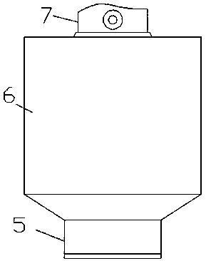
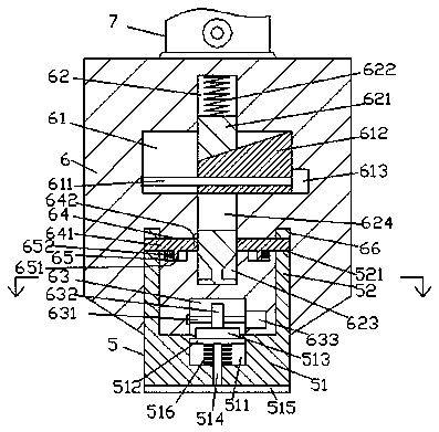
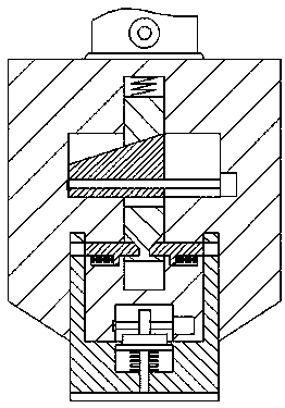
[0017] Such as Figure 1-Figure 4 As shown, a portable subgrade compacting machine of the present invention includes a tamping device with a boom 7 installed at the bottom of the boom 7, and the tamping device includes an upper body 6 and a tamping device for mating with the upper body 6 The lower body 5 is provided with a sinking groove 63 in the bottom end surface of the upper body 6, and the inner wall of the upper body 6 on the upper side of the sinking groove 63 is provided with a first sliding cavity 61 extending left and right. A second sliding cavity 62 extending up and down is formed in the middle of the cavity 61, and a lifting slider 621 is slidably connected in the second sliding cavity 62, and the second sliding block on the top of the lifting slider 621 A first spring 622 is connected to the cavity 62 with pressure fit. The middle position inside the lifting slider 621 is provided with an inclined-plane through chute 624. The top pressure inclined chute 623 is s...


PUM


Abstract

The invention discloses a portable subgrade compacting machine, which comprises a compacting device with a boom installed at the bottom of the boom. The compacting device includes an upper body and a lower body for matching connection with the upper body. A sinking groove is arranged in the end surface of the bottom of the upper body , the inner wall of the upper body on the upper side of the sinking tank is provided with a first sliding chamber extending left and right, and a second sliding chamber extending up and down is installed in the middle of the first sliding chamber, and the second sliding chamber is slidingly fitted and connected There is a lifting slider, and the first spring is press-fitted in the second sliding cavity on the top of the lifting slider. The middle position inside the lifting slider is provided with an inclined surface through the chute, and the inclined surface is connected to the lower side of the lifting slider. The end faces on both sides are symmetrically provided with top pressure inclined chute, and the first sliding cavity is slidably connected with an inclined surface pushing slider that extends into the inclined surface through the chute and is slidably connected; the present invention has simple structure and convenient operation. It is convenient to disassemble, maintain and overhaul, improve maintenance efficiency and improve the work efficiency of tamping.

Description

technical field [0001] The invention relates to the technical field of road construction machinery, in particular to a portable roadbed compactor. Background technique [0002] In road construction, in order to improve the pressure resistance of the road surface, the sand and gravel of the roadbed are generally tamped. The traditional tamping uses a manually moved vibratory compactor or a large hydraulic compactor. The manually moved vibratory compactor not only requires A large amount of labor, and the tamping accuracy is not high, the speed is slow, the tamping quality is poor, the working time is increased, the action surface is small, the energy consumption is relatively large through large-scale hydraulic tamping, the equipment utilization rate is low, and the construction cost of the road is increased. In addition, the traditional tamping machine has complex structure, poor operation flexibility, difficult disassembly and maintenance, and cannot meet the needs of exist...

Claims


Application Information

Patent Timeline
IPC IPC(8): E02D3/046
CPCE02D3/046
Inventor 张伟萍
Owner 张伟萍
Features
  • Generate Ideas
  • Intellectual Property
  • Life Sciences
  • Materials
  • Tech Scout
  • Unparalleled Data Quality
  • Higher Quality Content
  • 60% Fewer Hallucinations
Learn More