Cement grouting machine for maintenance

A cement grouting and fixing frame technology, which is applied in building maintenance, construction, building construction, etc., can solve the problems of no flow control valve, no screw feeding rod, and cement slurry overflow and waste in the grouting nozzle, so as to prevent Overflow waste, easy to control, not easy to clog the effect

Inactive Publication Date: 2018-03-06
CHENGDU BAIFULONG PRECISION MACHINERY CO LTD
View PDF0 Cites 6 Cited by
  • Summary
  • Abstract
  • Description
  • Claims
  • Application Information

AI Technical Summary

Problems solved by technology

[0003] Yet the existing cement grouting machine that is used for maintenance has some deficiencies in the use process, and the feeding pipe is mostly a horizontal structure, and the screw feeding rod is not provided inside, resulting in very stable feeding. The grout nozzle is not equipped with a flow control valve, and the grouting flow cannot be controlled according to the size of the crack, which may easily lead to overflow and waste of grout

Method used


Image

  • Cement grouting machine for maintenance
  • Cement grouting machine for maintenance

Examples


Embodiment Construction

[0018] The following will clearly and completely describe the technical solutions in the embodiments of the present invention with reference to the accompanying drawings in the embodiments of the present invention. Obviously, the described embodiments are only some, not all, embodiments of the present invention.

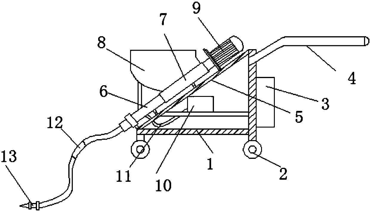
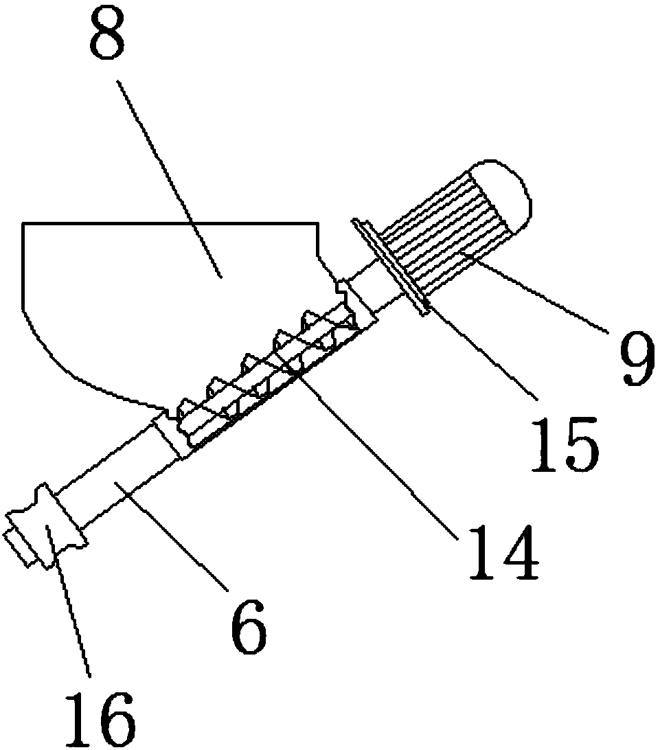
[0019] refer to Figure 1-2 , a cement grouting machine for maintenance, comprising a fixed frame 1, four corners of the bottom of the fixed frame 1 are provided with rollers 2, an electric control box 3 is fixed on the surface wall of the fixed frame 1, and the fixed frame 1 is located The top of the electric control box 3 is welded with a push handle 4, and the fixed frame 1 is welded with an installation slant plate 5, and the installation slant plate 5 is fixed with a feeding tube 6, and the feeding tube 6 is fixed with a bucket 8 through a casing 7. On the inclined plate 5, a feeding motor 9 is fixed on the top of the feeding pipe 6, and the feeding motor 9 is c...


PUM


Abstract

The invention discloses a cement grouting machine for maintenance, which comprises a fixed frame, four corners of the bottom of the fixed frame are provided with rollers, an electric control box is fixed on the surface wall of one side of the fixed frame, the fixed frame A push handle is welded on the frame above the electric control box, an installation slant plate is welded on the fixed frame, and a feeding pipe is fixed on the installation slanting board, and a barrel is fixed on the feeding pipe through a sleeve. A feeding motor is fixed on the top of the feeding pipe on the slant plate, and the feeding motor is connected with the screw feeding rod in the feeding pipe through a reducer, and the feeding pipe is connected with a grouting nozzle through a high-pressure pipe. In the present invention, through the setting of the flow control valve, the flow rate of the grout nozzle injected into the grout can be controlled according to the size of the grouting crack, so as to prevent the grout from overflowing and wasting due to the excessive flow rate. The cement grouting machine is reasonable in design, easy to control, and easy to use. convenient.

Description

technical field [0001] The invention relates to the technical field of cement grouting machines, in particular to a cement grouting machine for maintenance. Background technique [0002] At present, with the rapid development of the construction industry, architects pay more attention to the deformation of expansion joints in building structures than ever before. The rise and fall of temperature caused by thermal expansion and contraction, the rise and fall of the foundation, the shaking of the top of high-rise buildings, earthquakes, etc., all cause The expansion joint deformation of the building. For this reason, the research and development personnel have studied the above problems in depth, combined with the actual situation, fully considered the careful development, and absorbed the advanced design concepts and experience of foreign countries in this field, so the cement mortar spraying grouting machine came into being. The cement mortar spraying grouting machine is sui...

Claims


Application Information

Patent Timeline
Patent Type & Authority Applications(China)
IPC IPC(8): E04G23/02
CPCE04G23/0211
Inventor 不公告发明人
Owner CHENGDU BAIFULONG PRECISION MACHINERY CO LTD
Why Eureka
Try Eureka