
Orthogonal linear scanning CL imaging system and analysis method

A linear scanning and imaging system technology, applied in the field of scanning imaging, can solve the problems of low flexibility of the system, the resolution of reconstructed images needs to be improved, and there is no structural complexity and cost of the focusing system, so as to achieve the effect of improving the flexibility of the system.

Active Publication Date: 2018-03-06
CHONGQING UNIV
View PDF12 Cites 7 Cited by
  • Summary
  • Abstract
  • Description
  • Claims
  • Application Information

AI Technical Summary

Problems solved by technology

However, it has some disadvantages: the curvature of the C-arm of the system is fixed, and the position of the ray source is fixed, so the distance from the system ray source to the track of the flat panel detector cannot be adjusted, so the field of view (Field of View, FOV) is not variable, resulting in inflexibility of the system High; although these systems have achieved good results in medical and industrial applications, they have not focused on system structure complexity, cost, etc.
In addition, the traditional linear scanning CL system only uses a single scan to obtain projection data. Due to the limited projection data obtained, the resolution of the reconstructed image needs to be improved.

Method used


Image

  • Orthogonal linear scanning CL imaging system and analysis method
  • Orthogonal linear scanning CL imaging system and analysis method
  • Orthogonal linear scanning CL imaging system and analysis method

Examples


Embodiment Construction

[0045] The preferred embodiments of the present invention will be described in detail below with reference to the accompanying drawings.

[0046] 1 imaging model

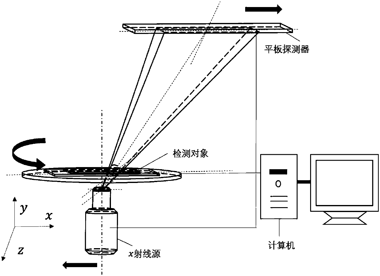
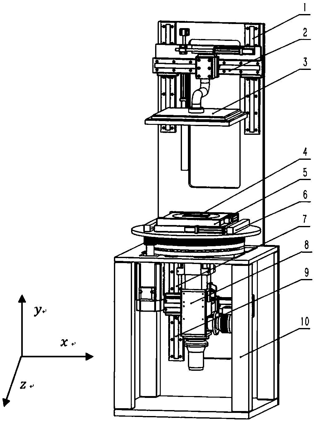
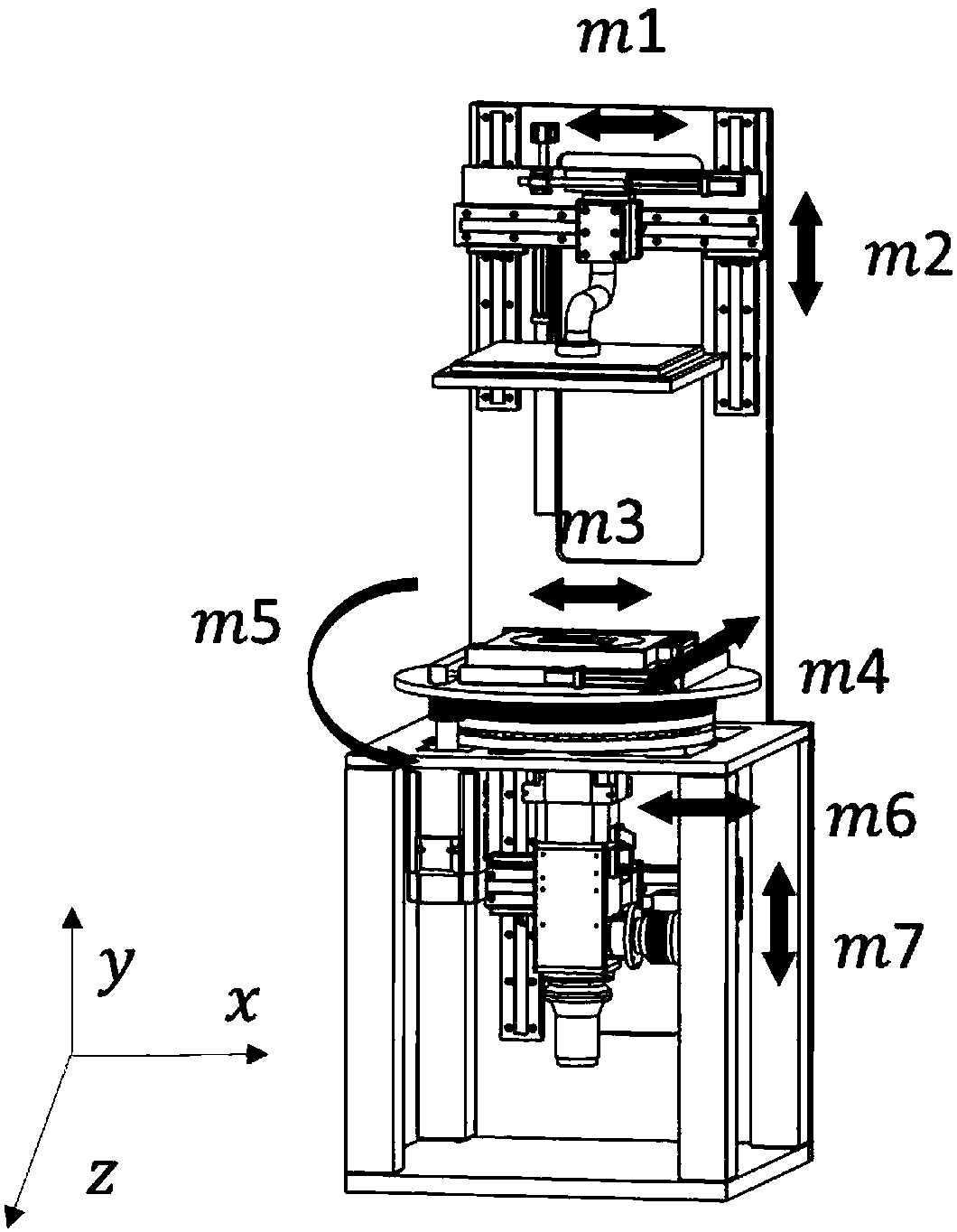
[0047] The data acquisition method is based on the relative parallel linear motion of the X-ray source and detector. Such as figure 1 As shown, the X-ray source is located at the bottom, with two degrees of freedom, that is, moving left and right and up and down and emitting cone-beam X-rays upward; the stage is located above the X-ray source, and can realize translational and rotational movements; Above the stage, the attenuated X-rays are received synchronously. Such as figure 2 As shown, 1 is the movement mechanism of the flat panel detector in the y direction, 2 is the scanning movement mechanism of the flat panel detector in the x direction, 3 is the flat panel detector, 4 is the detection object, 5 is the movement mechanism of the detection object in the z direction, and 6 is the x direction of the detecti...


PUM


Abstract

The invention relates to an orthogonal linear scanning CL imaging system and an analysis method, and belongs to the field of scanning imaging. An X-ray source is positioned at the bottommost end, andhas two degrees of freedom, i.e., the X-ray source moves left and right and up and down and emits a cone beam X-ray upwards; a carrying stage is positioned above the X-ray source, and can implement plane translational motion and rotating motion; a flat panel detector is positioned above the carrying stage, and has two degrees of freedom, i.e., the flat panel detector moves left and right and up and down and synchronously receives the attenuated X-ray. The method comprises the steps that: in a first step, an object is fixed, the flat panel detector and the ray source take relatively parallel motion along sliding rails and acquire one group of projection data; in a second step, after the object rotates by 90 degrees in a plane of the carrying stage, the flat panel detector and the ray sourcealso take relatively parallel motion and acquire a second group of projection data. According to the orthogonal linear scanning CL imaging system and the analysis method, an amplification ratio and view field size can be regulated according to detection demands so as to adapt to different detection demands. By adopting orthogonal linear CL scanning, CL resolving power in two directions can be obtained.

Description

technical field [0001] The invention belongs to the field of scanning imaging, and relates to a CL imaging system and an analysis method for orthogonal linear scanning. Background technique [0002] In recent years, the research and development of X-ray computerized tomography imaging technology has attracted people's attention. A typical CL system mainly includes three parts: X-ray source, detector and stage. The detection object is placed on the stage between the X-ray tube and the flat panel detector, and the X-rays generated by the X-ray tube are collected and stored by the detector after being attenuated by the object. Its characteristic is that the object to be scanned is a flat object, and the CL system scans in a non-coaxial manner, and the X-ray passes through in a direction at a certain angle to the normal of the flat sample plane, and the X-ray source and detector rotate synchronously Or do simple relative parallel movement to scan the sample from multiple angle...

Claims


Application Information

Patent Timeline
IPC IPC(8): G01N23/044
CPCG01N23/04
Inventor 刘丰林王少宇伍伟文冉磊龚长城
Owner CHONGQING UNIV
Learn More