Directional Radar Transmitting and Receiving System
A directional radar and receiving system technology, applied in radio wave measurement systems, instruments, etc., can solve the problems of low anti-interference ability, easy false triggering, etc., to achieve the effect of ensuring accuracy, not easy to trigger, and avoiding signal interference
- Summary
- Abstract
- Description
- Claims
- Application Information
AI Technical Summary
Problems solved by technology
Method used
Image
Examples
Embodiment 1
[0047] Embodiment 1: Description of the hardware part of the present invention:
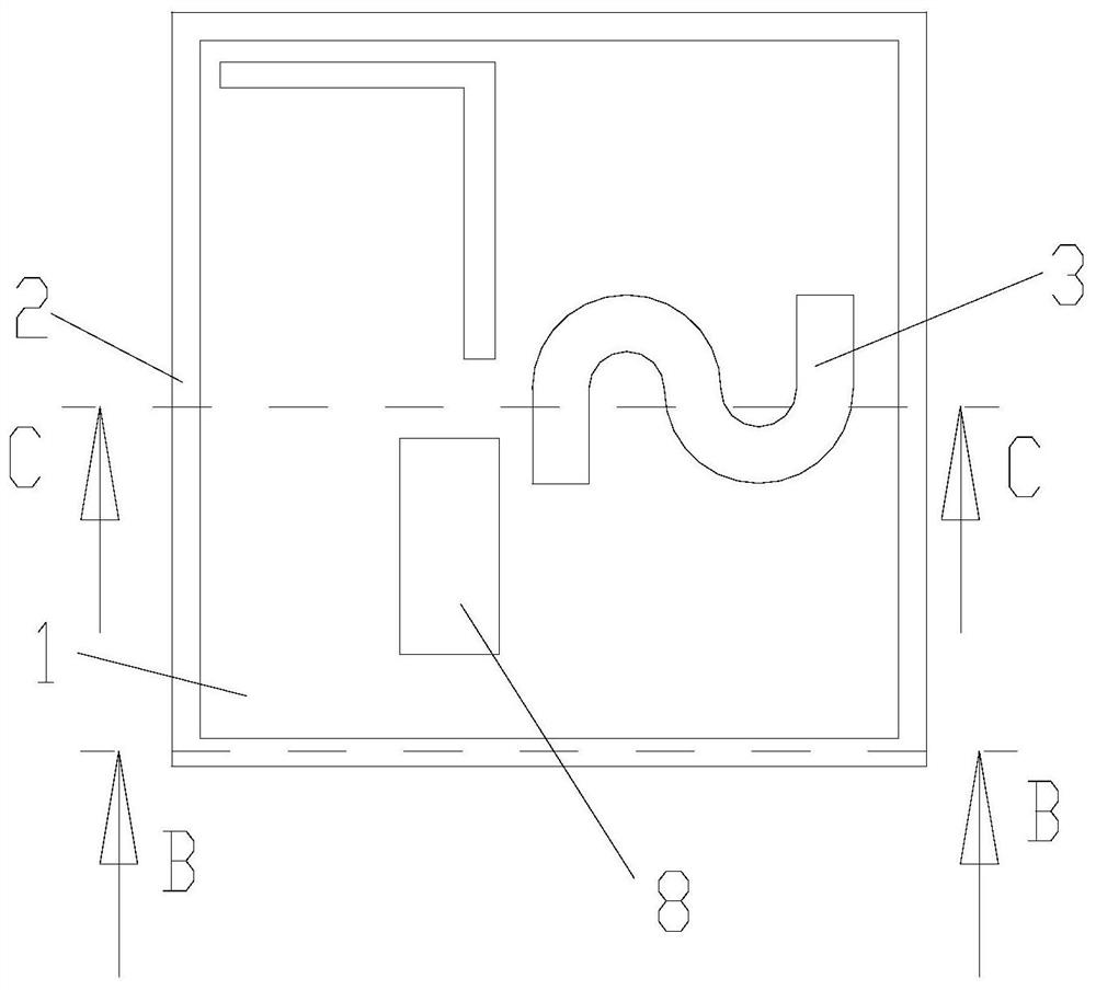
[0048] Such as figure 1 , figure 2 , image 3 , Figure 4 , Figure 5 , Image 6 , Figure 7 , Figure 8 , Figure 9 As shown, the directional radar transmitting and receiving system provided in this embodiment includes an induction board 1 integrated with a microwave oscillator, a transmitting antenna and a receiving antenna, and copper wire one 2 and copper wire two 3 are respectively laid on the induction board 1 as transmitting Antenna and receiving antenna, the transmitting antenna transmits the high-frequency microwave signal through the transmitting antenna, and the receiving antenna reflects the high-frequency microwave signal back through the receiving antenna, and a shielding plate 4 is installed on one side of the induction plate 1, and the shielding plate 4 and the transmitting The antenna and the receiving antenna are located on both sides of the induction plate 1, the shiel...
Embodiment 2
[0061] Embodiment 2: Principle description of the software part of the present invention.
[0062] Such as Figure 1 to Figure 10 As shown, the directional radar transmitting and receiving system of the present invention includes an induction board and a main control board, wherein: a microwave oscillator, a transmitting antenna and a receiving antenna are integrated on the induction board; a signal amplification circuit, a main control board are integrated on the main control board Chip and switch circuit; the microwave oscillator of the sensor board emits high-frequency microwaves through the transmitting antenna, and the reflected frequency shift signal is received by the receiving antenna distributed on the sensor board, and the frequency shift signal is mixed and detected to form a pulse wave The signal is output to the signal amplification circuit on the main control board, and after the signal amplification circuit is processed, it is sent to the main control chip for p...
PUM
 Abstract
Description
Claims
Application Information
 - R&D
- Intellectual Property
- Life Sciences
- Materials
- Tech Scout
- Unparalleled Data Quality
- Higher Quality Content
- 60% Fewer Hallucinations
Browse by: Latest US Patents, China's latest patents, Technical Efficacy Thesaurus, Application Domain, Technology Topic, Popular Technical Reports.
© 2025 PatSnap. All rights reserved.Legal|Privacy policy|Modern Slavery Act Transparency Statement|Sitemap|About US| Contact US: help@patsnap.com


