Paper currency or ticket detection device

A bill and banknote technology, which is applied in the field of banknote or bill detection equipment, can solve the problems of banknote or bill identification and inability to inspect, and achieve the effect of low hardware cost, stable and reliable performance, and high detection and recognition rate

Inactive Publication Date: 2018-03-06
BEIJING NUFRONT SOFTWARE TECH
View PDF0 Cites 2 Cited by
  • Summary
  • Abstract
  • Description
  • Claims
  • Application Information

AI Technical Summary

Problems solved by technology

The current banknote or bill identification module mainly relies on contact sensors such as infrared penetration, ultraviolet fluorescence, and magnetic coding for detection, and does not use image mode to identify the authenticity of banknotes or bills; for the identification of banknotes or bills, Especially for the recognition of important features such as banknote denomination and serial number, most of them are detected by CIS (Contact Image Sensor), that is, contact image sensor.
And the new 2015 version of RMB has many features, and the existing banknote detectors can't check it

Method used


Image

  • Paper currency or ticket detection device
  • Paper currency or ticket detection device

Examples


Embodiment 1

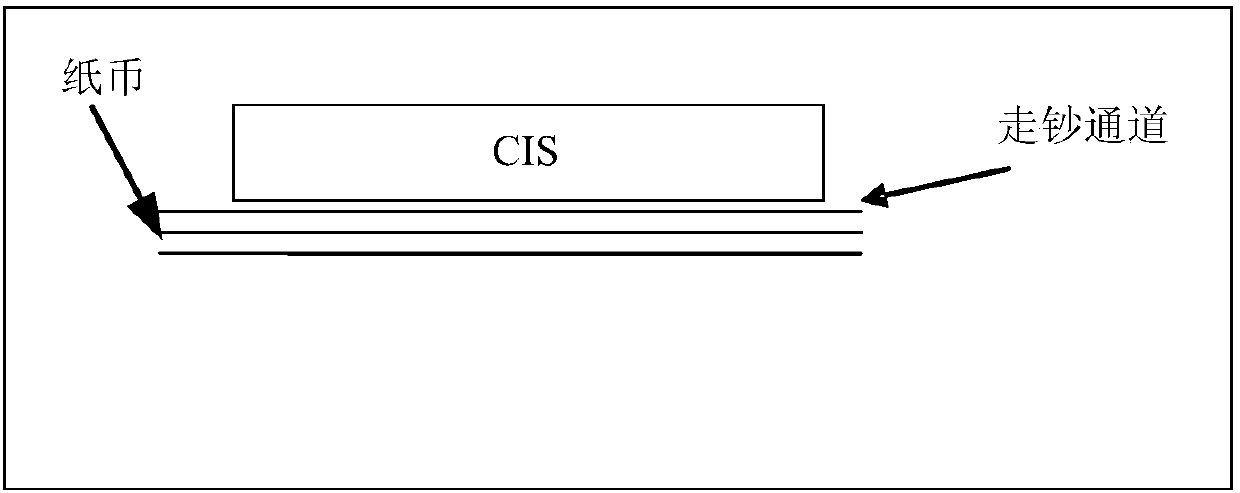
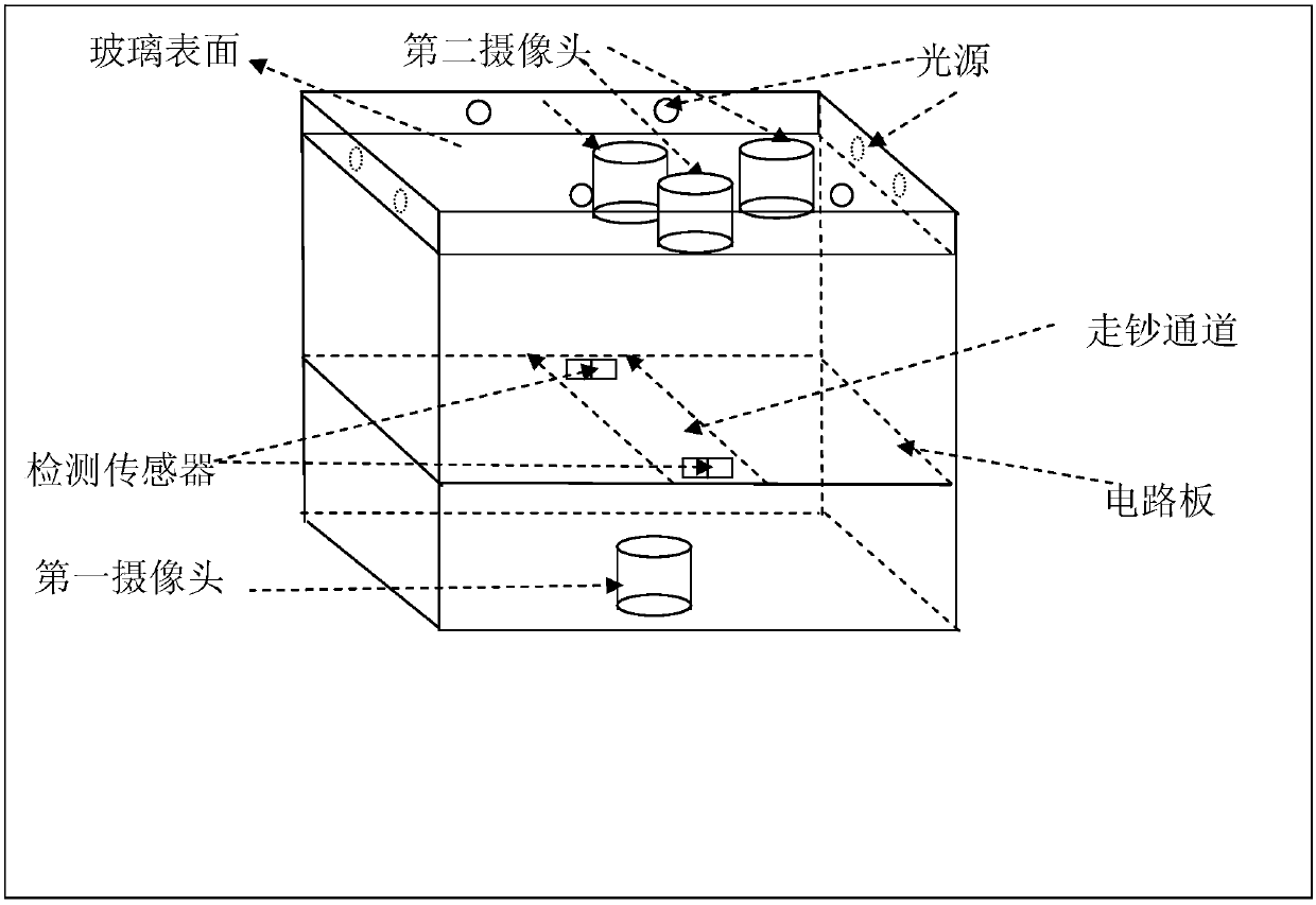
[0027] figure 1 , 2 It is a structural schematic diagram of the banknote or bill detection device according to the present invention. Such as figure 1 As shown, the device includes: a glass plate, a cash passage, multiple light sources, a first camera, a second camera and a circuit board:

[0028] Such as figure 2 as shown,

[0029] The glass plate is set directly above the cash passage; multiple light sources are set around the surface of the glass plate; the second camera is located on the lower surface of the glass;

[0030] The first camera and the circuit board are located directly below the cash passage;

[0031] The detection sensor is set at the entrance of the banknote-feeding channel to detect banknotes or bills entering the banknote-feeding channel;

[0032] The light source, the first camera, the second camera and the detection sensor are respectively connected with the circuit board.

[0033] Preferably, include:

[0034] When it is detected that bankno...

Embodiment 2

[0057] Embodiment 2 is described by taking the detection of banknotes of the 2015 edition as an example.

[0058] When it is detected that the banknotes of the 2015 version pass through the entrance of the banknote passage, the detection sensor sends an indication signal, and the light source is turned on, and the light source illuminates the banknotes of the 2015 version to be tested, and triggers the first camera to use the light source to The transmitted light of the 2015 banknote starts to collect the first image on the banknote or bill, and sends the first image to the circuit board; after the circuit board receives the first image, it turns off the first camera and triggers all The second camera starts to collect the second image and the third image on the banknote or bill by using the reflected light reflected by the light source to the banknote of the 2015 version, and sends the second image and the third image to the circuit board ;

[0059] The circuit board analyze...


PUM


Abstract

The invention discloses a banknote and bill detection device, comprising: a glass plate, a banknote passing channel, a light source, a first camera, a second camera and a main board: the glass plate is arranged directly above the banknote passing channel; There are multiple light sources; the second camera is located on the lower surface of the glass to collect reflected images; the first camera and circuit board are located directly below the banknote-moving channel to collect light-transmitting images; the detection sensor is set at the entrance of the banknote-moving channel, It is used to detect banknotes or bills that enter the banknote-feeding channel; the light source, the first camera, the second camera, and the detection sensor are respectively connected to the circuit board. The invention has strong adaptability to currency types, low hardware cost, high detection and recognition rate, and stable performance. Reliable and other advantages.

Description

technical field [0001] The invention belongs to the field of photoelectric technology, and in particular relates to a banknote or bill detection device. Background technique [0002] At present, the identification of the authenticity of banknotes or bills and the identification of the characteristics of banknotes or bills have become important problems to be solved in the field of cash finance. The current banknote or bill identification module mainly relies on contact sensors such as infrared penetration, ultraviolet fluorescence, and magnetic coding for detection, and does not use image mode to identify the authenticity of banknotes or bills; for the identification of banknotes or bills, In particular, the recognition of important features such as the denomination and serial number of banknotes is mostly detected by CIS (Contact Image Sensor), that is, a contact image sensor. And the new 2015 version of RMB has multiple features, and the existing banknote detectors cannot...

Claims


Application Information

Patent Timeline
Patent Type & Authority Applications(China)
IPC IPC(8): G07D7/20
CPCG07D7/2008G07D7/2016
Inventor 罗旻鲍东山
Owner BEIJING NUFRONT SOFTWARE TECH
Why Eureka
Try Eureka