Automatic double-row type lead acid battery pole group arranging process
A lead-acid battery, automatic arrangement technology, applied in the direction of lead-acid battery, lead-acid battery construction, sustainable manufacturing/processing, etc. High efficiency, ingenious structure, and the effect of improving work efficiency
- Summary
- Abstract
- Description
- Claims
- Application Information
AI Technical Summary
Problems solved by technology
Method used
Image
Examples
Embodiment 1
[0056] The embodiments are described below with reference to the accompanying drawings. The embodiments shown below do not limit the invention content described in the claims. required for the solution.
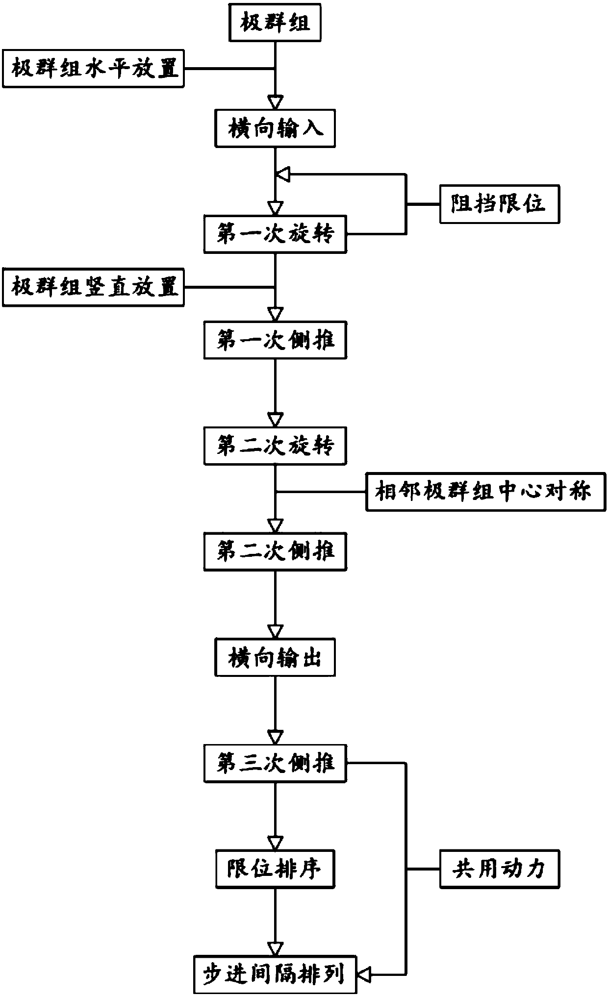
[0057] Such as figure 1 As shown, a double-row lead-acid battery electrode group automatic arrangement process, including:
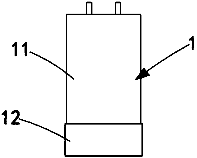
[0058] Step 1, the input process, the pole group 11 wrapped in PVC film is inserted into the fixed sleeve 12 to form the pole group unit 1, and the pole group unit 1 is horizontally placed on the input component 31, and the input component 31 is used for horizontal input;
[0059] Step 2, the first rotation process, the pole group unit 1 is horizontally transported by the input assembly 31 to the first rotation station at its output end, and the pole group unit 1 is inserted into the placement groove 4112 of the carrier plate 4111, The carrying plate 4111 is rotated 90° around its hinge with the first installation part 21, and the horizontally placed ...
Embodiment 2
[0077] Reference manual attached figure 1 A double-row lead-acid battery electrode group automatic arrangement system according to the second embodiment of the present invention is described.
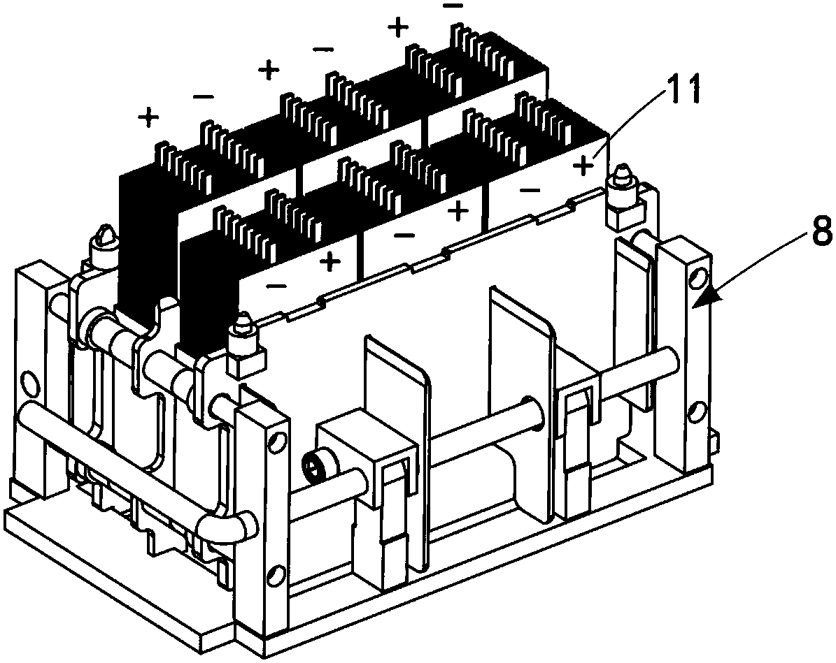
[0078] Such as figure 2 , image 3 , Figure 4 and Figure 5 As shown, a double-row lead-acid battery pole group automatic arrangement system includes a pole group unit 1, and the pole group unit 1 includes a pole group 11, a fixed sleeve 12 and several magnetic counterweights 13, and the pole group 11 Inserted in the fixed sleeve 12, the magnetic counterweights 13 are all arranged at the bottom of the fixed sleeve 12, and also include:
[0079] Mounting frame 2, described mounting frame 2 comprises the first mounting part 21 that is positioned at the front end and the second mounting part 22 of rear end and the placing part 23 that is vertically arranged with this second mounting part 22, and described first mounting part 21 is Arranged in a line, the second installation part 22 ...
Embodiment approach
[0124] Such as Figure 16 As shown, as a preferred implementation manner, the second lateral thrust assembly 52 includes:
[0125] The second side thrust cylinder 521, the second side thrust cylinder 521 is arranged on one side of the rotating disk 421, and it is arranged facing the output assembly 32; and
[0126] The second side push plate 522, the second side push plate 522 is fixedly connected with the end of the cylinder push rod of the second side push cylinder 521, and it is pushed by the second side push cylinder 521 to rotate the The pole group unit 1 on the disc 421 is output to the input terminal of the input assembly 32 .
[0127] It should be noted that the second side pushing cylinder 521 drives the second side pushing plate 522 to push and output the pole group unit 1 on the rotating disk 421, and push and transport the pole group unit 1 to the output assembly 32.
[0128] Such as Figure 16 As shown, as a preferred implementation manner, the third lateral th...
PUM
 Abstract
Description
Claims
Application Information
 - R&D
- Intellectual Property
- Life Sciences
- Materials
- Tech Scout
- Unparalleled Data Quality
- Higher Quality Content
- 60% Fewer Hallucinations
Browse by: Latest US Patents, China's latest patents, Technical Efficacy Thesaurus, Application Domain, Technology Topic, Popular Technical Reports.
© 2025 PatSnap. All rights reserved.Legal|Privacy policy|Modern Slavery Act Transparency Statement|Sitemap|About US| Contact US: help@patsnap.com


