
Ventilation and pressure relief device, switch cabinet body and switch cabinet

A technology of pressure relief device and switchgear, which is applied to electromechanical devices, substation/distribution device shell, substation/switch layout details, etc. , the effect of ensuring safety

Active Publication Date: 2018-03-06
HENAN SENYUAN ELECTRIC CO LTD
View PDF9 Cites 2 Cited by
  • Summary
  • Abstract
  • Description
  • Claims
  • Application Information

AI Technical Summary

Problems solved by technology

[0004] The purpose of the present invention is to provide a ventilation and pressure relief device to solve the problems in the prior art that the ventilation and pressure relief device is large in size and occupy a large space; the purpose of the present invention is also to provide a switch cabinet using the device

Method used


Image

  • Ventilation and pressure relief device, switch cabinet body and switch cabinet
  • Ventilation and pressure relief device, switch cabinet body and switch cabinet
  • Ventilation and pressure relief device, switch cabinet body and switch cabinet

Examples


Embodiment Construction

[0036] The implementation of the ventilation and pressure relief device, the switch cabinet body and the switch cabinet of the present invention will be further described below in conjunction with the accompanying drawings.

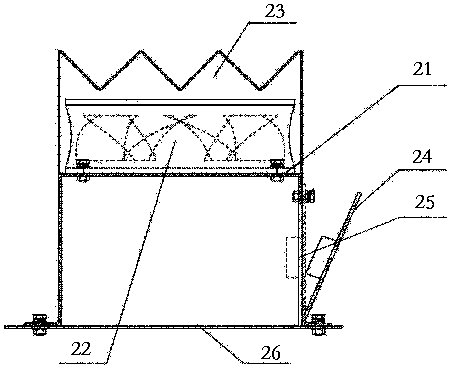
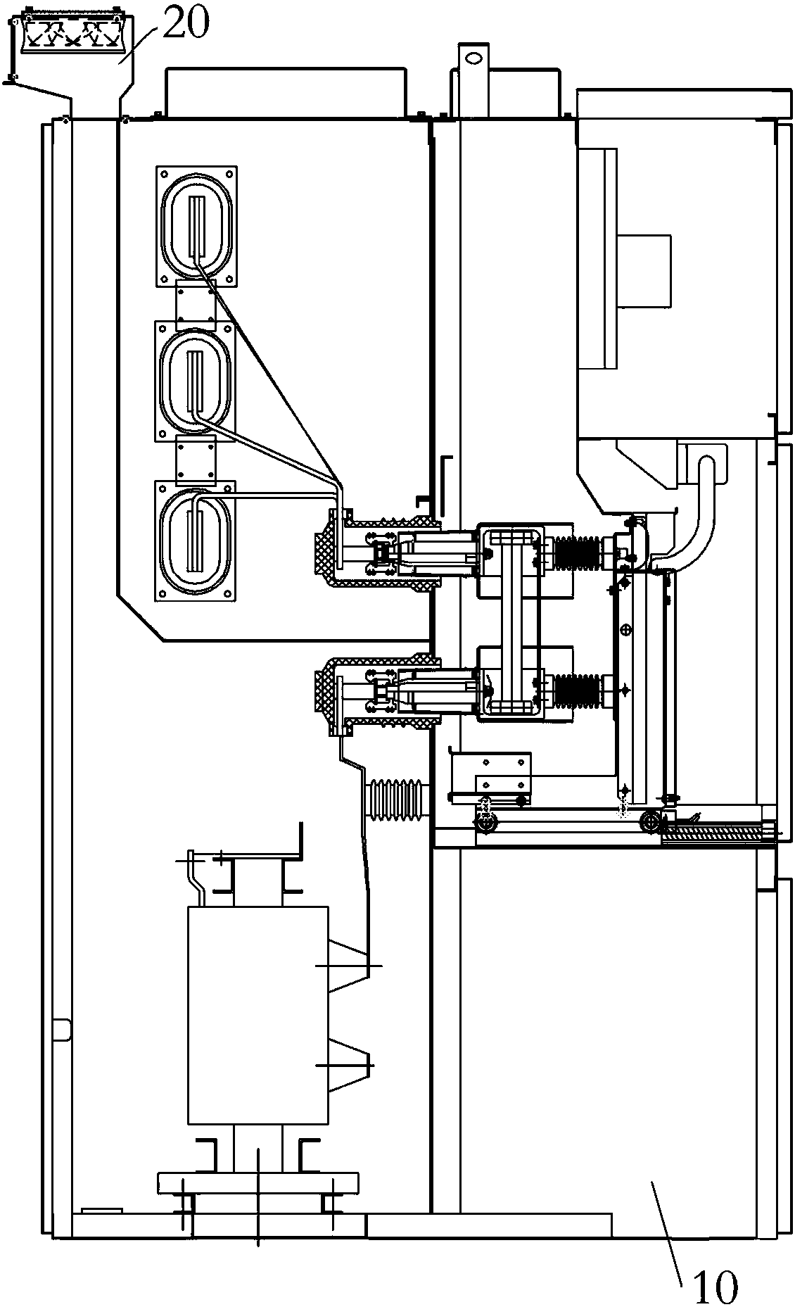
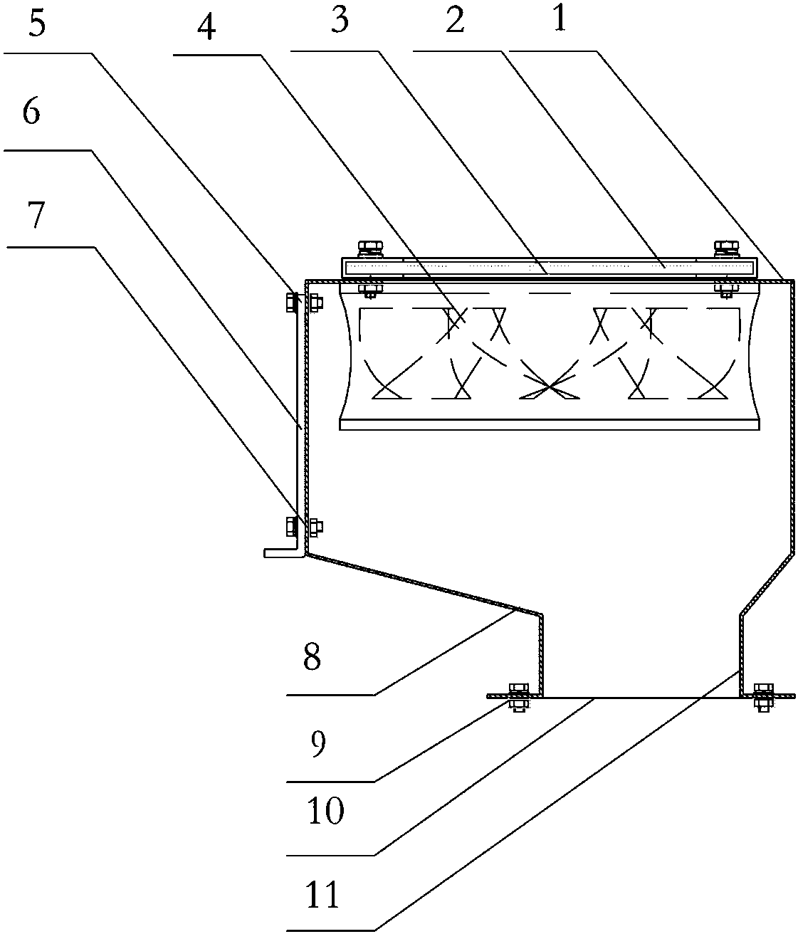
[0037] The specific embodiment of switchgear of the present invention, as Figure 2 to Figure 6 As shown, the switch cabinet includes a cabinet body 10 and electrical components arranged in the cabinet body 10. In order to relieve pressure and dissipate heat to the switch cabinet, a switch cabinet vent is provided on the top of the cabinet body 10, and a ventilation port is provided outside the switch cabinet vent. Pressure relief device 20. The ventilation and pressure relief device 20 includes a pressure relief cover. For the convenience of processing, the pressure relief cover in this embodiment includes a pressure relief cover top cover 1 with folds on both sides and a first pressure relief cover welded on the folds on both sides. Side plate 8, secon...


PUM


Abstract

The invention relates to a ventilation and pressure relief device, a switch cabinet body and a switch cabinet. The ventilation and pressure relief device comprises a pressure relief cover, wherein a pressure relief cover ventilation hole is formed in the pressure relief cover, a fan is assembled in the pressure relief cover in a suspension way, a baffle plate is arranged at the bottom of the pressure relief cover and is used for being fixed at a ventilation hole of the switch cabinet, and a plurality of baffle plate ventilation holes are formed in the baffle plate and are used for communicating the switch cabinet and the pressure relief cover. The fan is assembled in the pressure relief cover in the suspension way, the pressure relief cover ventilation hole is formed in the pressure reliefcover, ventilation and heat dissipation of the switch cabinet are ensured, and the volume of the pressure relief cover is reduced; and meanwhile, the baffle plate is arranged at the bottom of the pressure relief cover and is provided with the baffle plate ventilation holes, a related part can be effectively prevented from falling to the switch cabinet by the baffle plate, the safety of the switchcabinet is ensured, and the problems of large volume and large occupied space of the ventilation and pressure relief device in the prior art are solved.

Description

technical field [0001] The invention relates to a ventilation and pressure relief device, a switch cabinet body and a switch cabinet. Background technique [0002] With the development of smart grids, medium and high voltage switchgears are widely used, and people put forward higher and more comprehensive requirements for the safety of switchgears. In order to ensure the safety when the internal current of the switchgear reaches a certain level, the method of installing a fan in the cable room on the top of the switchgear is often used to cool the switchgear. The fan is suspended and assembled on the top of the switch cabinet, and then the fan dust cover is installed on the fan to prevent external dust from entering the inside of the switch cabinet, which can play a better heat dissipation and dust-proof function for the switch cabinet. However, when the fan on the top of the suspended switchgear fails, the fan or fan components may fall off the cable chamber, causing the s...

Claims


Application Information

Patent Timeline
Patent Type & Authority Applications(China)
IPC IPC(8): H02B1/56H02B1/30H02K5/22
CPCH02B1/30H02B1/306H02B1/565H02K5/225
Inventor 时菲刘洋赵宝红马超薛羊
Owner HENAN SENYUAN ELECTRIC CO LTD
Learn More