A New Topology of AC Power Electronic Transformer

A technology of power electronics and topological structure, applied in the field of traction drive system, can solve the problems of power electronic traction transformer machine volume reduction, low reliability of DC/DC conversion unit, and difficulty of faulty converters, etc.

Active Publication Date: 2020-07-14
BEIJING JIAOTONG UNIV
View PDF4 Cites 0 Cited by
  • Summary
  • Abstract
  • Description
  • Claims
  • Application Information

AI Technical Summary

Problems solved by technology

However, this circuit structure has the following problems: 1. The number of medium / high-frequency transformers and low-voltage switching devices is large; 2. Since each medium / high-frequency transformer needs to be designed according to the same high-voltage insulation level, the high-voltage Insulation limits the further reduction of the volume of the medium / high frequency transformer. In this case, the number of medium / high frequency transformers is large, which is not conducive to the further reduction of the overall volume of the power electronic traction transformer; 3. The DC / DC conversion unit consists of Multiple DC / DC converters are input in series and outputs are connected in series. When any DC / DC converter fails, the faulty converter is difficult to be effectively isolated, and the reliability of the DC / DC conversion unit is not high.

Method used


Image

  • A New Topology of AC Power Electronic Transformer
  • A New Topology of AC Power Electronic Transformer
  • A New Topology of AC Power Electronic Transformer

Examples


Embodiment Construction

[0052] The present invention will be described in further detail below in conjunction with the accompanying drawings.

[0053] Attached below figure 1 -5. Explain in detail the topology of the new AC power electronic transformer. It should be emphasized that the following description is only exemplary and not intended to limit the scope of the invention and its application.

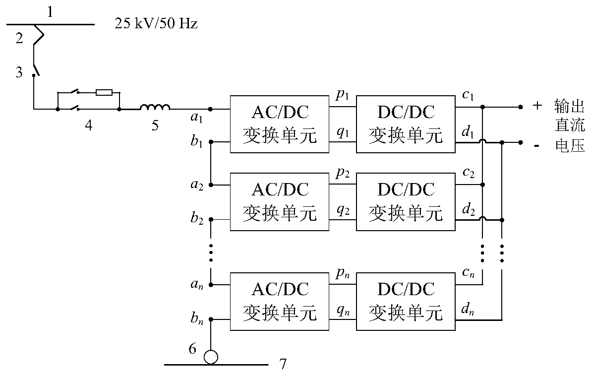
[0054] figure 1 It is a schematic diagram of the topology structure of the power electronic traction transformer used in the first scenario. The power electronic traction transformer is composed of n AC / DC conversion units and n DC / DC conversion units. Among them, the AC input side a of n AC / DC conversion units j , b j In series in sequence, the DC output side c of n DC / DC conversion units j 、d j sequentially connected in parallel. The jth AC / DC conversion unit shares the DC bus p with the jth DC / DC conversion unit j ,q j , where j=1,2,...,n.

[0055] Such as figure 1As shown, the AC input ter...


PUM


Abstract

The invention proposes a novel topological structure of an AC power electronic transformer. According to different application occasions, the basic topological structure of the AC power electronic transformer proposed by the present invention can be divided into two types, including a new type of power electronic traction transformer topology applied to the traction drive system of high-speed EMUs, and a new topology applied to the interconnected three-phase medium / high voltage AC Novel Three-Phase AC Power Electronic Transformer Topology for Power Grids and LVDC Grids. The basic topological structure proposed by the present invention can realize the self-removal of any faulty converter in the DC / DC conversion unit without using a DC bypass contactor. On the basis of the basic topology, it is possible to arbitrarily reduce but at least retain the bidirectional isolated DC in a group of DC / DC conversion units by sharing the half-bridge arms of the voltage equalizing converter and the cascaded isolated DC / DC converter. / DC converter, thereby reducing the number of medium / high frequency transformers and low voltage switching devices, thereby reducing the volume, weight and cost of AC power electronic transformers.

Description

technical field [0001] The invention relates to a novel topological structure of an AC power electronic transformer, which is suitable for interconnecting a medium / high voltage AC power grid and a low voltage DC power grid, and is also suitable for a traction drive system of a high-speed EMU. Background technique [0002] Power electronic transformer is a kind of power conversion device with high-frequency link, which can realize voltage conversion and electrical isolation. It has broad application prospects in traction drive system of EMU and AC-DC interconnection power system. According to the input and output voltage standards of power electronic transformers, they can be roughly divided into two categories: 1. DC power electronic transformers, whose input and output voltages are both DC; 2. AC power electronic transformers, whose input voltage is AC and output The voltage is DC. [0003] DC power electronic transformers can be used in auxiliary power supply systems for ...

Claims


Application Information

Patent Timeline
Patent Type & Authority Patents(China)
IPC IPC(8): H02J3/36H02M5/458H02M3/335
CPCH02J3/36H02M3/3353H02M5/4585H02M1/0058Y02B70/10Y02E60/60
Inventor 刘建强张捷频杨景熙赵楠汪洋
Owner BEIJING JIAOTONG UNIV
Why Eureka
Try Eureka