
Isolated bridge type three-port DC converter

A DC converter and three-port technology, which is applied in the direction of conversion equipment with intermediate conversion to AC, can solve the problems of three-port electrical isolation and voltage matching, limited soft switching range, and complex control.

Active Publication Date: 2015-09-23
HUAZHONG UNIV OF SCI & TECH
View PDF4 Cites 2 Cited by
  • Summary
  • Abstract
  • Description
  • Claims
  • Application Information

AI Technical Summary

Problems solved by technology

[0003] In the prior art, there are the following two three-port circuits: one is a three-port circuit based on two half-bridge structures, in which the primary half-bridge of the isolation transformer is connected to the renewable energy source, the secondary half-bridge is connected to the load, and the storage The energy device is connected in parallel with the primary side voltage dividing capacitor; the charge and discharge of the energy storage device can be realized by controlling the two switch tubes of the primary side bridge arm; The disadvantage of this structure is that it cannot provide electrical isolation and voltage matching for all three ports, and the working range of its soft switch is limited
[0004] The other is a three-port circuit based on a multi-winding transformer. By connecting the three-winding transformer with three full-bridge structures, and then respectively connecting renewable energy, energy storage devices, and loads, the electrical isolation and communication between the three ports can be realized. The voltage is matched, and the energy flow between the ports can be controlled by controlling the phase relationship between the three full bridges; however, the coupling between the three transformer windings of this structure is serious, and there is a circulating current, resulting in reduced efficiency and complicated control

Method used


Image

  • Isolated bridge type three-port DC converter
  • Isolated bridge type three-port DC converter
  • Isolated bridge type three-port DC converter

Examples


Embodiment 2

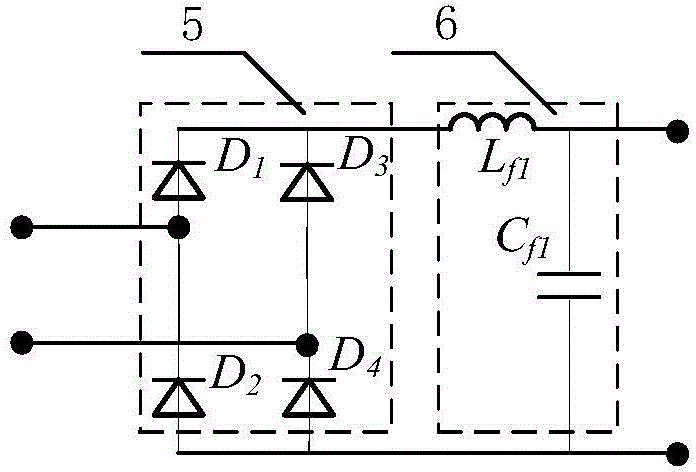
[0091] The rectifier circuit 5 in embodiment 2 is the same as the rectifier circuit in embodiment 1, and is composed of four rectifier diodes D 1 、D 2 、D 3 and D 4 Form; The connection between the elements is also the same as in Embodiment 1;

[0092] The filter adopts C filter 7, and the filter capacitor C f3 The first terminal of the filter capacitor is equivalent to the first terminal and the third terminal of the filter, connected to the first output terminal of the rectifier circuit, and its connection terminal is used as the output positive terminal of the first output unit 12, which is used to connect the load positive terminal. terminal; the second terminal of the filter capacitor is connected to the second output terminal of the rectifier circuit 5, and its connection terminal is used as the output negative terminal of the first output unit 12 for connecting to the negative terminal of the load.

[0093] The second output unit 13 adopts a full-bridge circuit 8, an...

Embodiment 3

[0108] The rectifier circuit 5 in embodiment 3 is also the same as the rectifier circuit in embodiment 1, and is composed of four rectifier diodes D 1 、D 2 、D 3 and D 4 Form; The connection between the elements is also the same as in Embodiment 1;

[0109] The filter adopts LC filter 6, and the LC filter consists of filter inductor L f1 and filter capacitor C f1 Formed in series, the first end of the LC filter is connected to the first output end of the rectification circuit; the second end of the filter is connected to the second output end of the rectification circuit 5, and its connection end is used as the output negative end of the first output unit 12 , used to connect the negative terminal of the load; the third terminal of the filter is used as the positive output terminal of the first output unit 12, and is used to connect the positive terminal of the load.

[0110] The second output unit 13 adopts a half-bridge circuit, and the half-bridge circuit 9 has the adva...

Embodiment 4

[0125] The rectifier circuit 5 in embodiment 4 is also the same as the rectifier circuit in embodiment 1, and is composed of four rectifier diodes D 1 、D 2 、D 3 and D 4 Composition; The connection between the components is also the same as in Embodiment 1; the filter adopts a C filter 7, which is composed of a filter capacitor C f3 The first terminal of the filter capacitor is equivalent to the first terminal and the third terminal of the above-mentioned filter, connected to the first output terminal of the rectifier circuit 5, and its connection terminal is used as the positive output terminal of the first output unit 12 for connecting the load Positive terminal; the second terminal of the filter capacitor is connected to the second output terminal 1 of the rectifier circuit 2 , the connection terminal of which is used as the negative output terminal of the first output unit 12 for connecting to the negative terminal of the load.

[0126] The second output unit 13 adopts ...


PUM


Abstract

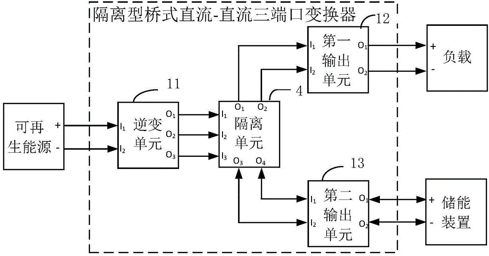
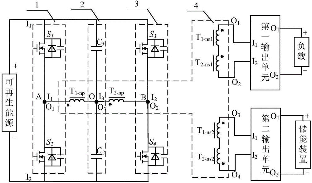
The invention discloses an isolated bridge type three-port DC converter which comprises an inversion unit, an isolation unit, a first output unit and a second output unit, the port at one side of the inversion unit is used for connecting a renewable energy source, the port at the other side of the inversion unit is connected with the isolation unit, the port at one side of the first output unit is connected with the isolation unit, the port at the other side of the first output unit is used for connecting a load, the port at one side of the second output unit is connected with the isolation unit, the port at the other side of the second output unit is used for connecting an energy storage device, the isolation unit is formed by two three-winding transformers, primary-side windings of the two three-winding transformers are connected in series, secondary-side windings of the two three-winding transformers are crossed in a group way and inversely and mutually connected in series, therefore, an output port and the energy storage device share complementary pulse, circulation among the renewable energy source, the energy storage device and the load is eliminated, and energy loss brought by the circulation is reduced.

Description

technical field [0001] The invention belongs to the technical field of direct current conversion, and more specifically relates to an isolated bridge type three-port direct current converter. Background technique [0002] Renewable energy is currently being used more and more widely. However, there are contradictions between the discontinuity and instability of renewable energy and the load that requires stable energy supply. It is necessary to introduce energy storage devices to balance between renewable energy and loads. Generally, a three-port circuit that simultaneously connects renewable energy, energy storage devices, and loads is used to solve this contradiction. [0003] In the prior art, there are the following two three-port circuits: one is a three-port circuit based on two half-bridge structures, in which the primary half-bridge of the isolation transformer is connected to the renewable energy source, the secondary half-bridge is connected to the load, and the st...

Claims


Application Information

Patent Timeline
IPC IPC(8): H02M3/28
Inventor 陈宇张鹏程康勇
Owner HUAZHONG UNIV OF SCI & TECH
Learn More