High-frequency power source of resonant coupling type wireless power transmission device

A wireless power transmission and coupling technology, which is applied to circuit devices, output power conversion devices, and AC power input into DC power output, etc., can solve the problems of complex circuits, high costs, and large losses, and achieve a simple circuit structure. , the effect of low cost

Inactive Publication Date: 2015-04-22
SOUTH CHINA UNIV OF TECH +1
View PDF5 Cites 3 Cited by
  • Summary
  • Abstract
  • Description
  • Claims
  • Application Information

AI Technical Summary

Problems solved by technology

Existing inverter circuits such as half-bridge inverter circuits and full-bridge inverter circuits, when they work at such a high frequency, the switching loss of the switch tube and the loss of the filter circuit will become very high
Moreover, these circuits use many switching tubes and components. When used as a high-frequency power source, the circuit is more complicated, the cost is higher, and the loss is large.

Method used


Image

  • High-frequency power source of resonant coupling type wireless power transmission device
  • High-frequency power source of resonant coupling type wireless power transmission device
  • High-frequency power source of resonant coupling type wireless power transmission device

Examples


Embodiment Construction

[0013] The specific implementation of the present invention will be further described below in conjunction with the accompanying drawings, but the implementation and protection of the present invention are not limited thereto.

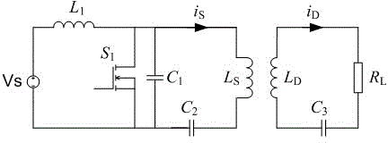
[0014] like figure 1 The circuit shown is a high-frequency power source circuit diagram of a resonantly coupled wireless power transmission device, which includes a MOSFET switch tube S 1 , snubber capacitance C 1 , transmitting coil Ls, first tuning capacitor C2, energy storage filter inductor L 1 , receiving coil L D and the second tuning capacitor C3. It is characterized in that the MOSFET switch tube S 1 The drain and snubber capacitor C 1 One end of the connection, and then connected to one end of the transmitting coil Ls. MOSFET switch tube S 1 The source and snubber capacitors C 1 The other end of the first tuning capacitor C2 is connected, and then connected to one end of the first tuning capacitor C2. The other end of the first tuning...


PUM


Abstract

The invention provides a high-frequency power source of a resonant coupling type wireless power transmission device. The high-frequency power source is formed by a switching tube, a snubber capacitor, a transmitting coil, a tuning capacitor and an energy storage filter inductor, high-frequency sine alternating currents can be output, soft switching of the switching tube can be achieved, and efficiency of the high-frequency power source is improved. The high-frequency power source is simple in structure and low in cost and is provided with a small number of elements, and the loss is close to zero, so that the high-frequency power source is very suitable for serving as an alternating current excitation source of a transmitting coil of the wireless power transmission device.

Description

technical field [0001] The invention belongs to the field of wireless power transmission applications and relates to a circuit of a high-frequency power source. Background technique [0002] The resonant coupling wireless power transmission technology requires the transmitting coil and the receiving coil to work in a high-frequency state, and its frequency reaches above 1 MHz. Therefore, the power source that provides alternating current for the transmitting coil must also work in a high-frequency state, and must be able to provide 1 MHz. Sinusoidal alternating current above Hertz. Existing inverter circuits, such as half-bridge inverter circuits and full-bridge inverter circuits, when they operate at such a high frequency, the switching loss of the switching tube and the loss of the filter circuit will become very high. Moreover, these circuits use many switching tubes and components, and when used as a high-frequency power source, the circuit is more complicated, the cost...

Claims


Application Information

Patent Timeline
Patent Type & Authority Applications(China)
IPC IPC(8): H02M7/537H02J17/00H02J50/12
CPCH02M7/537H02M1/0058Y02B70/10
Inventor 肖文勋张波刘红伟郭上华
Owner SOUTH CHINA UNIV OF TECH
Why Eureka
Try Eureka