Synchronous rectification BOOST converter, synchronous rectification control circuit and method

A synchronous rectification and control circuit technology, applied in the direction of converting DC power input to DC power output, control/regulation systems, instruments, etc., can solve the problems of low efficiency, low amplitude, and large current RMS, and achieve high efficiency. Effect

Active Publication Date: 2018-03-06
MORNSUN GUANGZHOU SCI & TECH
View PDF5 Cites 14 Cited by
  • Summary
  • Abstract
  • Description
  • Claims
  • Application Information

AI Technical Summary

Problems solved by technology

When the input voltage is wide, the monotonous increase or decrease of the frequency will cause the reverse current I of the inductor when the switch tube M2 is turned off within the entire input voltage range. l_min There are large fluctuations
Monotonically increasing frequency will cause reverse current I at high input v

Method used


Image

  • Synchronous rectification BOOST converter, synchronous rectification control circuit and method
  • Synchronous rectification BOOST converter, synchronous rectification control circuit and method
  • Synchronous rectification BOOST converter, synchronous rectification control circuit and method

Examples


Embodiment 1

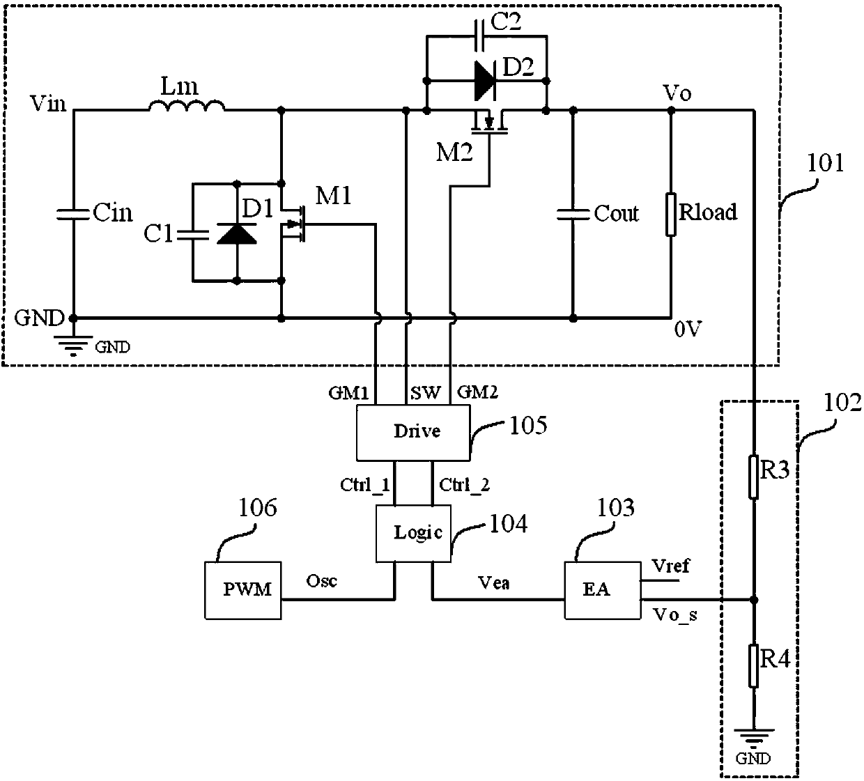
[0045] like Image 6 As shown, it is a functional block diagram of a synchronous rectification control circuit applied to a BOOST converter according to Embodiment 1 of the present invention. A synchronous rectification BOOST converter includes a main power unit 101 and a synchronous rectification control circuit. The synchronous rectification control circuit includes an output detection unit 102 , error amplification unit 103 , logic control unit 104 , drive circuit unit 105 , input detection unit 107 and nonlinear modulation unit 108 . Wherein, the input end of the output detection unit 102 is drawn as the first input end of the synchronous rectification control circuit, the input end of the input detection unit (107) is drawn as the second input end of the synchronous rectification control circuit, and the first input end of the drive circuit unit (105) One output end is drawn as the first output end of the synchronous rectification control circuit, the second output end of...

Embodiment 2

[0075] like Figure 11 Shown is a functional block diagram of a synchronous rectification control circuit applied to a BOOST converter in Embodiment 2 of the present invention. The difference from Embodiment 1 is that the input detection unit 107 is for input current detection. The detection circuit of the input current is simple and can detect the real-time inductor current, so that the precision of the frequency control is higher.

[0076] Preferably, the input detection unit 107 may be composed of a resistor R5, a resistor R6, and a capacitor C3. One end of the resistor R5 is connected to the source of the main switch M1 and one end of the resistor R6, and the other end of the resistor R5 is connected to the input GND. The other end is connected to one end of the capacitor C3 and the input end of the nonlinear modulation unit 108 , and the other end of the capacitor C3 is connected to the input GND. The terminal voltage of capacitor C3 is used as the output signal V of the...


PUM


Abstract

The invention provides a synchronous rectification control circuit and method. The synchronous rectification control circuit comprises an output detection unit, an error amplifying unit, a logic control unit and a driving circuit unit; the output detection unit is connected between the output positive end of a main power unit and the first input end of the error amplifying unit; the output end ofthe error amplifying unit is connected with the first input end of the logic control unit; the first output end and the second output end of the logic control unit are connected with the first input end and the second input end of the driving circuit unit respectively; the first output end and the second output end of the driving circuit unit are connected with gates of switching tubes M1 and M2 respectively; the third output end of the driving circuit unit is connected with the drain of the switching tube M1 and the source of the switching tube M2 respectively; the synchronous rectification control circuit also comprises an input detection unit and a nonlinear modulation unit; the output end of the input detection unit is connected with the input end of the nonlinear modulation unit; andthe output end of the nonlinear modulation unit is connected with the second input end of the logic control unit.

Description

technical field [0001] The invention relates to the field of switching converters, in particular to a synchronous rectification control circuit and method for a synchronous rectification BOOST converter. Background technique [0002] With the rapid development of the field of power electronics, the application of switching converters is becoming more and more extensive, especially people put forward more requirements for switching converters with high power density, high reliability and small size, and the switches in the converter Loss is usually the main factor limiting the frequency increase and volume reduction of converters, so soft switching technology has attracted more and more attention from the industry. [0003] At present, synchronous rectification BOOST circuit is usually used in the boost converter to meet the soft switching characteristics, and its schematic diagram is as follows figure 1 shown. If the synchronous rectification switching tube M2 is turned o...

Claims


Application Information

Patent Timeline
IPC IPC(8): H02M3/158
CPCH02M3/1588Y02B70/10
Inventor 何垒刘湘
Owner MORNSUN GUANGZHOU SCI & TECH
Why Eureka
Try Eureka