Intermediate logical interfaces in a virtual distributed router environment

A routing and interface technology, applied in the field of intermediate logical interfaces in a virtual distributed routing environment, can solve problems such as high delay, performance degradation, and low throughput

Active Publication Date: 2018-03-06
NICIRA
View PDF5 Cites 2 Cited by
  • Summary
  • Abstract
  • Description
  • Claims
  • Application Information

AI Technical Summary

Problems solved by technology

This creates unnecessary network traffic and results in higher latency and lower throughput, which significantly degrades the performance of applications running on the hypervisor
In general, this per

Method used


Image

  • Intermediate logical interfaces in a virtual distributed router environment
  • Intermediate logical interfaces in a virtual distributed router environment
  • Intermediate logical interfaces in a virtual distributed router environment

Examples


Embodiment Construction

[0032] In the following description, numerous details are set forth for purposes of explanation. However, one of ordinary skill in the art will recognize that the present invention may be practiced without the use of these specific details. In other instances, well-known structures and devices are shown in block diagram form in order not to obscure the description of the invention with unnecessary detail.

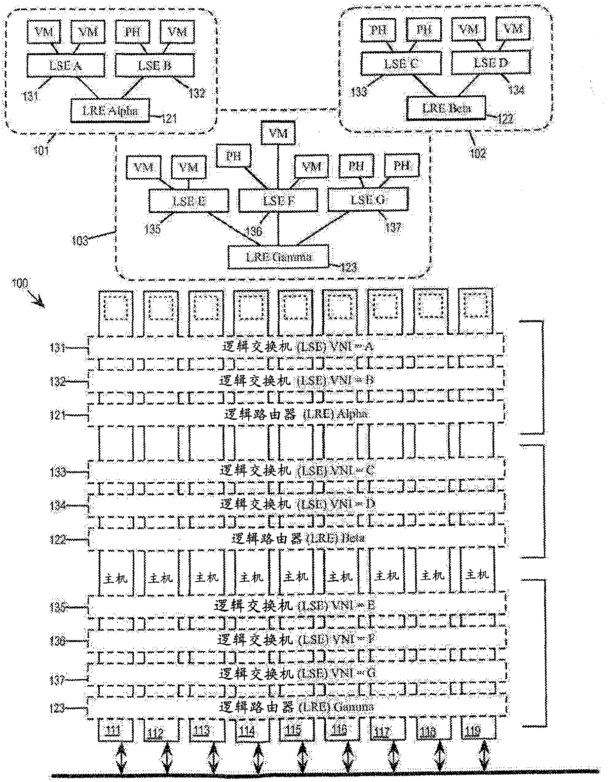
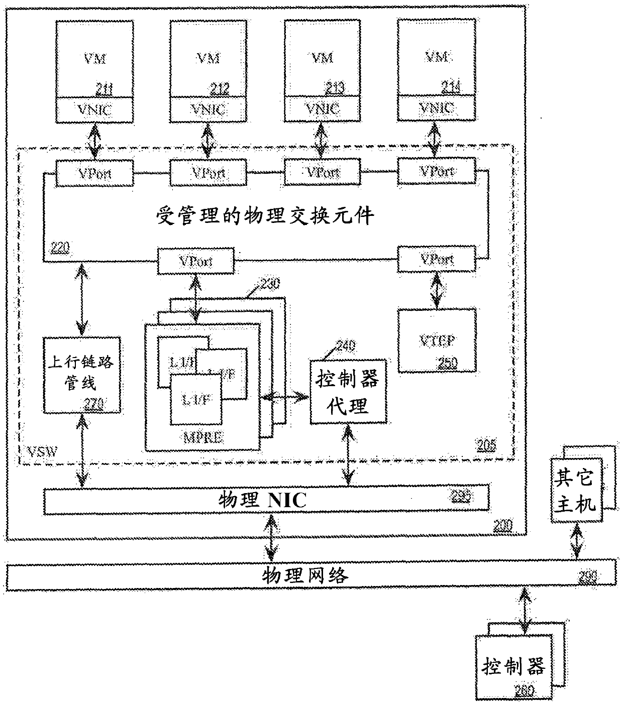
[0033] A virtual distributed router environment is one in which a logical router element (LRE) operates distributedly across different host machines as a virtual distributed router (VDR). Each host machine operates its own local instance of LRE as a Managed Physical Routing Element (MPRE) for performing L3 packet forwarding for VMs running on that host. In addition to operating distributed LREs, these various host machines also operate Logical Switching Elements (LSEs) as Distributed Virtual Switches (DVS). Each host machine operates its own local instance of LSE as a man...


PUM


Abstract

A LRE (logical routing element) that have LIFs that are active in all host machines spanned by the LRE as well as LIFs that are active in only a subset of those spanned host machines is provided. A host machine having an active LIF for a particular L2 segment would perform the L3 routing operations for network traffic related to that L2 segment. A host machine having an inactive LIF for the particular L2 segment would not perform. L3 routing operations for the network traffic of the L2 segment.

Description

[0001] Vivek Agarwal, Ganesan Chandrashekhar, Rahul Korivi Subramaniyam, Howard Wang, Ram Dular Singh Background technique [0002] In a network virtualization environment, one of the more common applications deployed on a hypervisor is a 3-tier application, where the web tier, database tier, and application tier are on different L3 subnets. This requires IP (Internet Protocol) packets traveling from one virtual machine (VM) in one subnet to another VM in another subnet to first reach the L3 router, and then be forwarded using the L2MAC (Media Access Control) address to Destination VM. This is true even if the destination VM is hosted on the same host machine as the originating VM. This generates unnecessary network traffic and results in higher latency and lower throughput, which significantly degrades the performance of applications running on the hypervisor. In general, this performance degradation occurs whenever any two VMs in two different network segments (eg, differe...

Claims


Application Information

Patent Timeline
IPC IPC(8): H04L12/713H04L12/721H04L12/46G06F9/455H04L12/931H04L45/74H04L45/586H04L45/60
CPCG06F9/45558H04L12/4641H04L45/586H04L45/66H04L49/70H04L45/44G06F2009/45595H04L45/74H04L41/0895H04L45/04H04L45/38H04L47/33H04L69/325H04L41/0893
Inventor V·埃加瓦尔G·钱德拉谢卡尔R·K·萨布拉玛尼亚H·王R·D·辛格
Owner NICIRA
Why Eureka
Try Eureka