
Ultrasonic device, ultrasonic module, and ultrasonic measuring device

A technology of ultrasound and devices, applied in ultrasonic/sonic/infrasonic diagnosis, ultrasonic/sonic/infrasonic equipment control, material analysis using sound/ultrasonic/infrasonic, etc. It can solve problems such as reduced efficiency of ultrasonic transmission and reception

Active Publication Date: 2018-03-09
SEIKO EPSON CORP
View PDF11 Cites 2 Cited by
  • Summary
  • Abstract
  • Description
  • Claims
  • Application Information

AI Technical Summary

Problems solved by technology

[0010] As described above, when the ultrasonic transducer described in the above-mentioned Patent Document 1 is used as an ultrasonic transducer for both transmission and reception, or when an ultrasonic transducer of the same configuration is used for both transmission and reception, there is an increase in the transmission and reception efficiency of ultrasonic waves. Reduced subject

Method used


Image

  • Ultrasonic device, ultrasonic module, and ultrasonic measuring device
  • Ultrasonic device, ultrasonic module, and ultrasonic measuring device
  • Ultrasonic device, ultrasonic module, and ultrasonic measuring device

Examples


Embodiment Construction

[0055] Hereinafter, the ultrasonic measurement device according to the present embodiment will be described based on the drawings.

[0056] [Configuration of Ultrasonic Measuring Device]

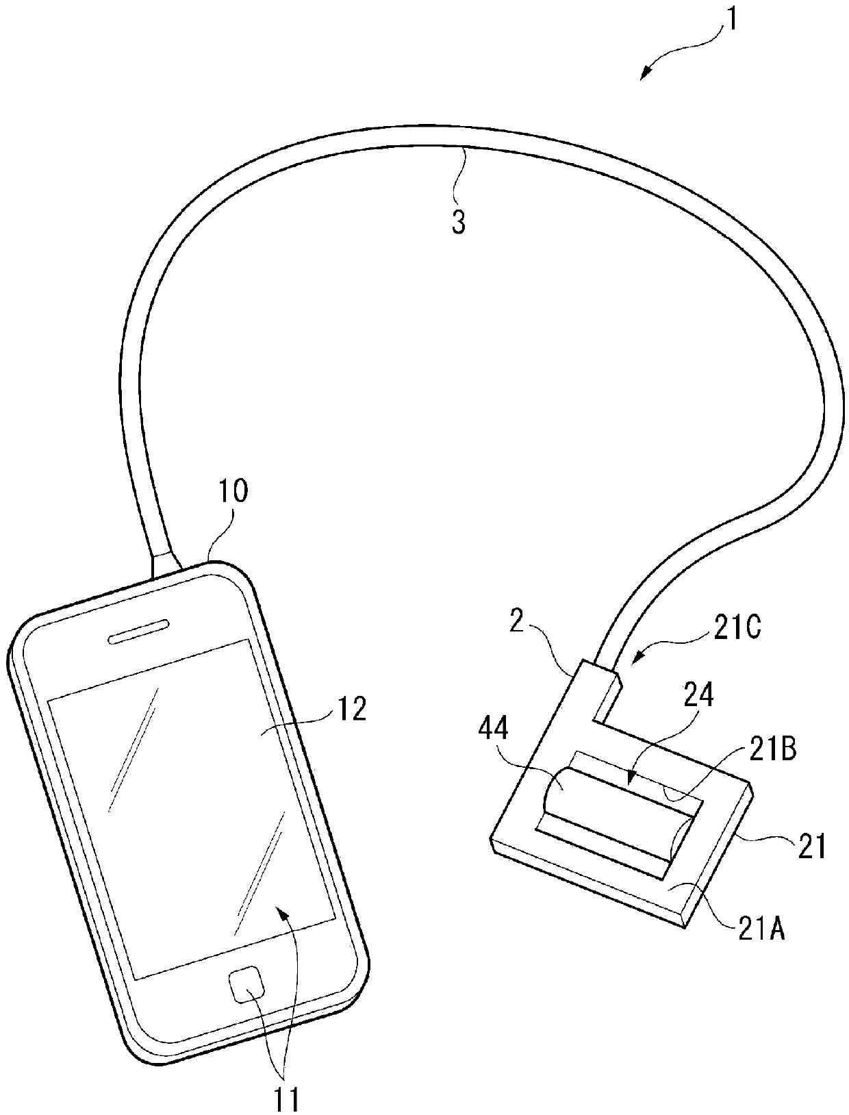
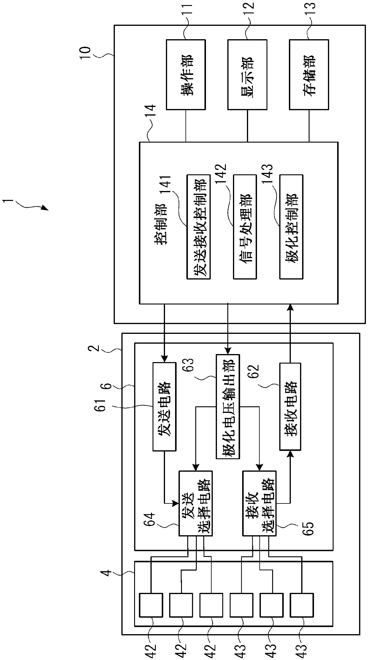
[0057] figure 1 It is a perspective view showing a schematic configuration of the ultrasonic measurement device 1 according to the present embodiment. figure 2 It is a block diagram showing a schematic configuration of the ultrasonic measurement device 1 according to the present embodiment.

[0058] Such as figure 1 As shown, the ultrasonic measurement device 1 of the present embodiment includes an ultrasonic probe 2 and a control device 10 electrically connected to the ultrasonic probe 2 via a cable 3 .

[0059] This ultrasonic measurement device 1 brings an ultrasonic probe 2 into contact with the surface of an object (for example, a living body), and sends ultrasonic waves from the ultrasonic probe 2 into the living body. Ultrasonic waves reflected by organs in the object (living bod...


PUM


Abstract

The invention provides an ultrasonic device that has high transmission / reception efficiency of ultrasonic waves, an ultrasonic module, and an ultrasonic measuring device. The ultrasonic device includes: a substrate provided with a first opening and a second opening; a support film that is provided on the substrate and closes the first opening and the second opening; a transmitting piezoelectric film that is provided on the support film at a position which overlaps the first opening when viewed in a thickness direction of the substrate and that is sandwiched between a pair of electrodes in thethickness direction of the substrate; and a receiving piezoelectric film that is provided on the support film at a position which overlaps the second opening when viewed in the thickness direction ofthe substrate and that is sandwiched between a pair of electrodes in an intersecting direction intersecting with the thickness direction of the substrate.

Description

technical field [0001] The invention relates to an ultrasonic device, an ultrasonic component, an ultrasonic measuring device and the like. Background technique [0002] Conventionally, as an ultrasonic transducer for transmitting and receiving ultrasonic waves, it is known to include a piezoelectric body sandwiched between a pair of electrodes, to transmit ultrasonic waves by applying a voltage between the electrodes to vibrate the piezoelectric body itself, or to transmit ultrasonic waves by An ultrasonic transducer of a so-called stacked piezoelectric body that detects an output voltage from a piezoelectric body to which ultrasonic waves are input and receives ultrasonic waves. However, such a stacked piezoelectric body requires a thick piezoelectric body, making it difficult to achieve thinning or miniaturization. [0003] In contrast, there is known an ultrasonic transducer using a thin-film piezoelectric film (for example, refer to Patent Document 1) composed of a vib...

Claims


Application Information

Patent Timeline
Patent Type & Authority Applications(China)
IPC IPC(8): A61B8/00A61B8/06B06B1/06B06B3/00
CPCA61B8/00A61B8/06A61B8/4427A61B8/4488B06B1/06B06B3/00G01N29/0681G01N29/221G01N2291/0426G01N2291/105A61B8/4483B06B1/0688A61B8/54G01N29/2437G01N2291/02466A61B8/4411A61B8/4494G01N2291/102
Inventor 宫泽弘伊藤浩中村友亮山田昌佳清濑摄内舩坂司
Owner SEIKO EPSON CORP
Learn More