
Water-mediated dielectric antenna and model establishment method thereof

A medium antenna, medium technology, applied in special data processing applications, radiating element structure, cooling/ventilation/heating transformation and other directions, can solve the problem of no reserved wireless network card, affecting the efficiency of antenna transmission and reception, and not easy to carry, etc. Portability and stability, save USB interface, save time effect

Pending Publication Date: 2018-06-01
CHENGDU GUORONG TECH
View PDF2 Cites 2 Cited by
  • Summary
  • Abstract
  • Description
  • Claims
  • Application Information

AI Technical Summary

Problems solved by technology

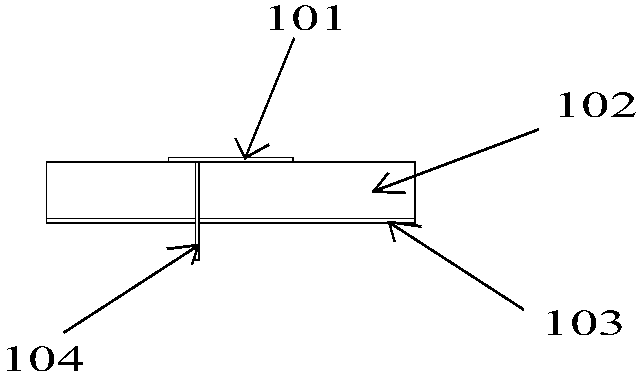
Traditional patch antennas such as figure 1 As shown, it includes a metal patch 101, a dielectric substrate 102, a ground layer 103, and a feeding probe 104. The dielectric substrate 102 is a filled dielectric material, and the metal patch 101 covering the dielectric substrate 102 serves as a radiation layer. Carry out wireless transmission and reception work; the traditional water dielectric antenna uses water to replace the filling material in the dielectric substrate 102, and its high dielectric constant can greatly reduce the size of the radiation patch, but using water as the filling material will seriously affect the Antenna Transceiver Efficiency
[0003] At present, most of the desktop computer motherboards on the market do not have a card slot reserved for a wireless network card. If the computer needs to connect to a wireless device, an external wireless network card with a USB interface is required, which requires an additional USB interface; in addition, an external wireless network card There is a monopole antenna, which is bulky and not easy to carry

Method used


Image

  • Water-mediated dielectric antenna and model establishment method thereof
  • Water-mediated dielectric antenna and model establishment method thereof
  • Water-mediated dielectric antenna and model establishment method thereof

Examples


Embodiment Construction

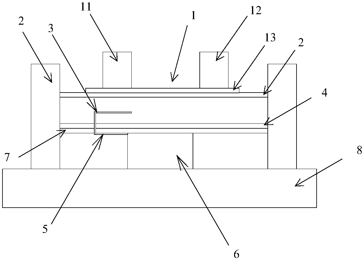
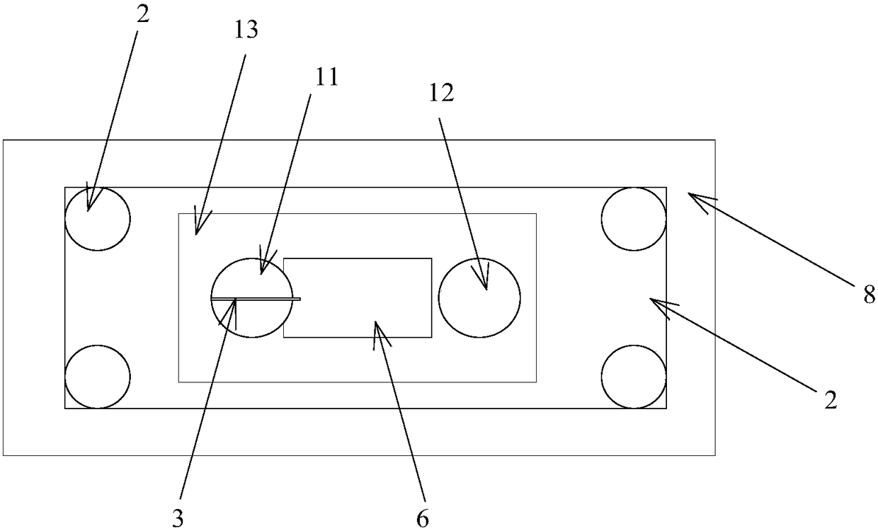
[0019] Such as figure 1 As shown, a dielectric antenna with water as the medium includes a water-cooled circulation structure 1, a support frame 2, a probe 3, and a ground layer 4; the support frame 2 includes a horizontal support frame and four columns fixedly supporting the four corners of the horizontal support frame, The four columns of the support frame 2 are fixedly connected to the ground layer 4 arranged horizontally below. The water-cooling circulation structure 1 includes a water inlet pipe 11 and an outlet pipe 12. The heat dissipation layer 13 is laid on the horizontal support frame of the support frame 2; there is an air layer between the ground layer 4 and the support frame 2, and an "L"-shaped probe 3 is arranged in the air layer, and the ground layer 4 is fixed and horizontally laid in turn The dielectric layer 7 and the signal layer 5, one end of the "L"-shaped probe 3 passes through the ground layer 4 and the dielectric layer 7 to connect to the signal layer ...


PUM


Abstract

The invention discloses a water-mediated dielectric antenna and a model establishment method thereof. The water-mediated dielectric antenna includes a water cooling and circulation structure, a supporting frame, an L-shaped probe, a grounding layer, a dielectric layer and a processor; water in the water cooling and circulation structure, replacing a metal layer in a traditional patch antenna, serves as a radiating medium; and air is adopted as a substrate, so that a wireless interface of any frequency to be achieved by changing the height of an air layer and changing the size of the water cooling and circulation structure. The invention also discloses a method for establishing the model of the dielectric antenna. According to the method, the model of the dielectric antenna can be established according to actual working requirements, so that the specific numerical values of the size parameters of the dielectric antenna can be obtained, and therefore, modeling and testing time before actual production can be saved.

Description

technical field [0001] The invention relates to a microstrip antenna, in particular to a dielectric antenna with water as a medium. Background technique [0002] The relative permittivity of water is around 81, and the greater the relative permittivity, the stronger its ability to bind electromagnetic fields. Traditional patch antennas such as figure 1 As shown, it includes a metal patch 101, a dielectric substrate 102, a ground layer 103, and a feeding probe 104. The dielectric substrate 102 is a filled dielectric material, and the metal patch 101 covering the dielectric substrate 102 serves as a radiation layer. Carry out wireless transmission and reception work; the traditional water dielectric antenna uses water to replace the filling material in the dielectric substrate 102, and its high dielectric constant can greatly reduce the size of the radiation patch, but using water as the filling material will seriously affect the Antenna transmit and receive efficiency. [...

Claims


Application Information

Patent Timeline
Patent Type & Authority Applications(China)
IPC IPC(8): H01Q1/36H05K7/20G06F17/50
CPCH01Q1/36H05K7/20218G06F30/367
Inventor 潘超姜丹丹郭明利常敏
Owner CHENGDU GUORONG TECH
Learn More