
3D manipulator for massage chair

A massage chair and manipulator technology, used in massage auxiliary products, roller massage, vibration massage, etc., can solve the problems of slippage, reduce transmission efficiency, affect the stability of massage chairs, etc., and achieve cost reduction, convenience and maintenance-free use. Effect

Pending Publication Date: 2018-03-09
温州市坤元电气制造有限公司
View PDF0 Cites 3 Cited by
  • Summary
  • Abstract
  • Description
  • Claims
  • Application Information

AI Technical Summary

Problems solved by technology

[0002] All kinds of health care massage chairs currently on the market include high-end luxury, mid-range multi-functional and low-grade simple, as well as large, medium and small. No matter which type of massage chair it is, due to the limitation of structure or layout, The 3D manipulators used have at least 2 or more V-ribbed belt transmission links. The transmission between the motor and the shaft on the 3D manipulator is realized by setting the V-ribbed belt and pulleys. The following deficiencies are eliminated: 1. Since the friction transmission between the V-belt and the pulley often occurs slipping, which reduces the transmission efficiency; 2. The friction between the V-belt and the pulley is likely to generate static electricity, thereby interfering with the control circuit; 3. Since the user cannot adjust the tightness of the V-ribbed belt, long-term use will easily cause the V-ribbed belt to loosen, which affects the stability of the massage chair and has a limited service life.
However, due to the setting of components such as drive motors, the structure of this 3D manipulator is relatively complicated, and the cost of accessories is relatively high, which is unfavorable for large-scale promotion and use.
Although most of the backrests of massage chairs on the market now use L guide rails or LS guide rails, which reduce the requirements for 3D movements, they still cannot well meet the massage comfort requirements of people of different heights and shapes, resulting in unsatisfactory massage effects.

Method used


Image

  • 3D manipulator for massage chair

Examples


Embodiment Construction

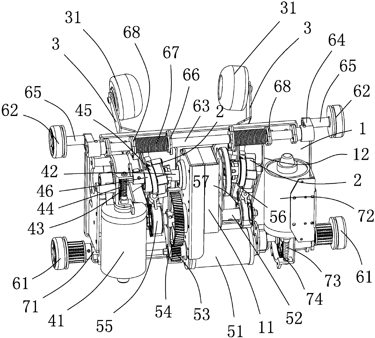
[0018] An embodiment of a 3D manipulator for a massage chair of the present invention is figure 1Shown: including walking board 1, two swing arms 2 are arranged at the rear end of walking board 1, and two swing arms 2 are pin-connected with crank arm 3 protruding to the front of walking board 1, and massage arm 3 is provided with The ball 31, the rear end of the walking board 1 is provided with a kneading component that drives the swing arm 2 to move to realize the kneading massage action, a knocking component that drives the swing arm 2 to move to realize the percussion massage movement, and drives the walking board 1 to move along the massage chair guide rail. The walking assembly for walking, the kneading assembly includes a kneading motor 41, a kneading eccentric shaft 42 and a kneading transmission mechanism, the output shaft of the kneading motor 41 is fixed with a first worm 43, and the kneading eccentric shaft 42 is fixed with a A worm 43 meshes with the first helical ...


PUM


Abstract

The invention discloses a 3D manipulator for a massage chair. The 3D manipulator comprises a traveling plate, wherein two swing arms are arranged at the rear end of the traveling plate; crank arms extending to the front of the traveling plate are hinged to the two swing arms; massage balls are arranged on the crank arms; a massage assembly for driving the swing arms to move to realize massage actions, a knocking assembly for driving the swing arms to move to realize knocking massage motion and a traveling assembly for driving the traveling plate to travel along guide rails of the massage chairare arranged at the rear end of the traveling plate. Compared with the prior art, the 3D manipulator for the massage chair is simple in structure, lower in cost, higher in transmission efficiency andlonger in service life, static electricity is not produced easily, and people with different heights and body sizes have better comfort.

Description

technical field [0001] The invention relates to a 3D manipulator used for a massage chair. Background technique [0002] All kinds of health care massage chairs currently on the market include high-end luxury, mid-range multi-functional and low-grade simple, as well as large, medium and small. No matter which type of massage chair it is, due to the limitation of structure or layout, The 3D manipulators used have at least 2 or more V-ribbed belt transmission links. The transmission between the motor and the shaft on the 3D manipulator is realized by setting the V-ribbed belt and pulleys. The following deficiencies are eliminated: 1. Since the friction transmission between the V-belt and the pulley often occurs slipping, which reduces the transmission efficiency; 2. The friction between the V-belt and the pulley is likely to generate static electricity, thereby interfering with the control circuit; 3. Since the user cannot adjust the tightness of the V-ribbed belt, long-term ...

Claims


Application Information

Patent Timeline
IPC IPC(8): A61H1/00A61H7/00A61H23/02A61H15/00
CPCA61H1/00A61H7/007A61H15/0078A61H23/006A61H23/02A61H2015/0042A61H2201/1659A61H2201/0149A61H2201/1207A61H2205/081
Inventor 林金明潘圣杰陈晓文
Owner 温州市坤元电气制造有限公司
Learn More