High-efficiency carbon fiber adsorption box

A carbon fiber and adsorption box technology, applied in the field of organic waste gas purification, can solve the problems of low flow rate and affecting the purification efficiency of equipment

Pending Publication Date: 2018-03-09
JIANGSU NANFANG COATING & ENVIRONMENT PROTECTION EQUIP
View PDF0 Cites 0 Cited by
  • Summary
  • Abstract
  • Description
  • Claims
  • Application Information

AI Technical Summary

Problems solved by technology

In order to ensure the best adsorption rate of carbon fiber, the slower the flow rate of the airflow passing through the carbon fiber, the better, but if the flow rate is too small, the volume or quantity of the box will increase. If

Method used


Image

  • High-efficiency carbon fiber adsorption box

Examples


Embodiment Construction

[0014] The present invention will be further described below in conjunction with the accompanying drawings and embodiments.

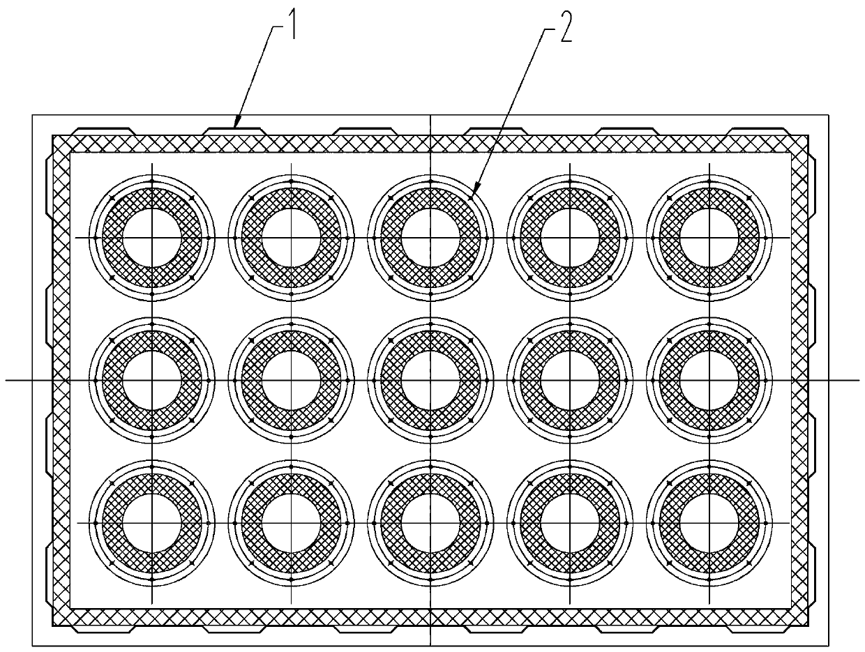
[0015] Such as figure 1 Shown: a high-efficiency carbon fiber adsorption box, including a box body 1 and a carbon fiber tube 2, the carbon fiber tube 2 is installed on the support plate in the box body 1, and is evenly distributed in the box body 1 of a standard adsorption box with a length of 2400 mm and a width of 1600 mm. Set 3*5 carbon fiber tubes 2, the carbon fiber tubes 2 are arranged vertically and horizontally in the box body 1 and the thickness of the carbon fiber layer on the carbon fiber tube 2 is smaller than the inner cavity radius of the carbon fiber tube 2 and the thickness of the carbon fiber layer is not less than 60mm; in the above structure, any The distance between the outer walls of the carbon fiber layer on two carbon fiber cylinders 2 is not less than twice the thickness of the carbon fiber layer on the carbon fiber cylinder 2, a...


PUM

PropertyMeasurementUnit
Thicknessaaaaaaaaaa

Abstract

The invention discloses a high-efficiency carbon fiber adsorption box, which includes a box body (1) and a carbon fiber tube (2), and the carbon fiber tube (2) is installed on a support plate inside the box body (1). 3*5 carbon fiber tubes (2) are evenly arranged in the box body (1) of a standard adsorption box with a width of 1600 mm. In the present invention, 15 carbon fiber cylinders are evenly arranged in the standard adsorption box with a length of 2400mm and a width of 1600mm, so that the filtering wind speed is lower than 0.2m/s, which is similar to a static state, and greatly improves the purification rate of carbon fiber to exhaust gas. Suitable for promotion and use.

Description

technical field [0001] The invention relates to the technical field of organic waste gas purification, in particular to a high-efficiency carbon fiber adsorption box with low air flow velocity and high purification efficiency. Background technique [0002] The carbon fiber tube in the adsorption box is hoisted on the support plate in the adsorption box, and the quantity is determined by each manufacturer. In order to ensure the best adsorption rate of carbon fiber, the slower the flow rate of the airflow passing through the carbon fiber, the better, but if the flow rate is too small, the volume or quantity of the box will increase. If the flow rate is too high, the organic waste gas in the airflow will not be able to be absorbed by the carbon fiber. It has already penetrated the carbon fiber layer, seriously affecting the purification efficiency of the equipment. Contents of the invention [0003] The purpose of the present invention is to provide a high-efficiency carbon...

Claims


Application Information

Patent Timeline
IPC IPC(8): B01D53/04
CPCB01D53/04B01D53/0407B01D53/0415B01D2253/102B01D2257/70B01D2259/403B01D2259/404B01D2259/4061
Inventor 周志娟
Owner JIANGSU NANFANG COATING & ENVIRONMENT PROTECTION EQUIP
Why Eureka
Try Eureka